Table of Contents
No load or Open circuit test
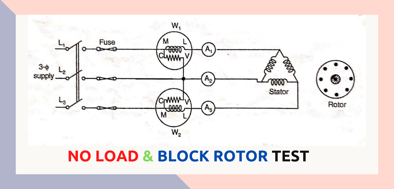
This test is performed on an induction motor, when the motor is running on No load. In this test, without connecting any load on the motor shaft, full voltage is applied across the stator winding terminals. The input power is measured by two wattmeter method. The ammeter measure the no load current & voltmeter gives the normal rated supply voltage.
- The I²R losses on the primary side are neglected as they vary with the square of the current, as we know that the No load current is 20-30 % of the full load current.
- Since the motor is running at no load, total input power is equals to constant iron losses, friction & windage losses of the motor.
Pconstant = Pi = P1 + P2 = Sum of two wattmeter reading

Since the power factor of the induction motor under No load condition is generally less than 0.5, one wattmeter will show negative reading. It is therefore, necessary to reverse the direction of current-coil terminals to take the reading.
As in the case of a transformer, the constant Rο & Xо can be calculated from the readings obtained in the No load test.
If Vinl = input line voltage
Pinl = total 3-phase input power at no-load
I0 = input line current.
Vip = input phase voltage
Pinl = √3 Vinl I0 cosΦ0
Iµ = I0 sinΦ0
Iω = I0 cosΦ0
Rо = Vip/Iω
Xo = Vip/Iμ
Blocked Rotor or Short circuit test
In this test, rotor of the motor is blocked. Low voltage is applied across the stator terminals through a there phase auto transformer voltage is gradually increased to a value so that full rated current flow through the windings. Since the rotor circuit is closed & not rotating this test is similar to short circuit test of a transformer.
The power input to the stator is mainly wasted as I²R loss in the stator & the rotor winding. The core losses are neglected at low voltage. The circuit diagram for blocked rotor test is shown in figure.

The sum of two wattmeter readings gives the total input power when the full load current is allowed to flow through the stator & rotor windings. From the data of the no load & blocked rotor tests the efficiency of the induction motor can be calculated.
Read Also :
- Three Phase Induction Motor || Construction & Working Principle
- Starting Methods of 3-Phase Induction Motor
- B.Tech – MDU Previous Year Question Papers Download


Comments (1)
Every weekend i used to visit this website, because i want enjoyment,
as this this web page conations really pleasant funny stuff too.