Table of Contents
There are several methods of control in MTDC systems. Only parallel MTDC systems are considered as these involve complexities in extending the existing control methods. The various methods suggested are reviewed below.
Read Also
MTDC | Introduction, Potential Applications, and Types
Current Margin Method
This is most widely considered the natural extension of control philosophy in a two-terminal system. One of the converter stations which is operating at the angle limit (minimum α or minimum y) determines the DC voltage (dependent on the AC voltage and the tap ratio) The remaining terminals operate as current controlling terminals. The current through the voltage setting terminal (say n) is given by
In = -Σn-1j = 1 Ij
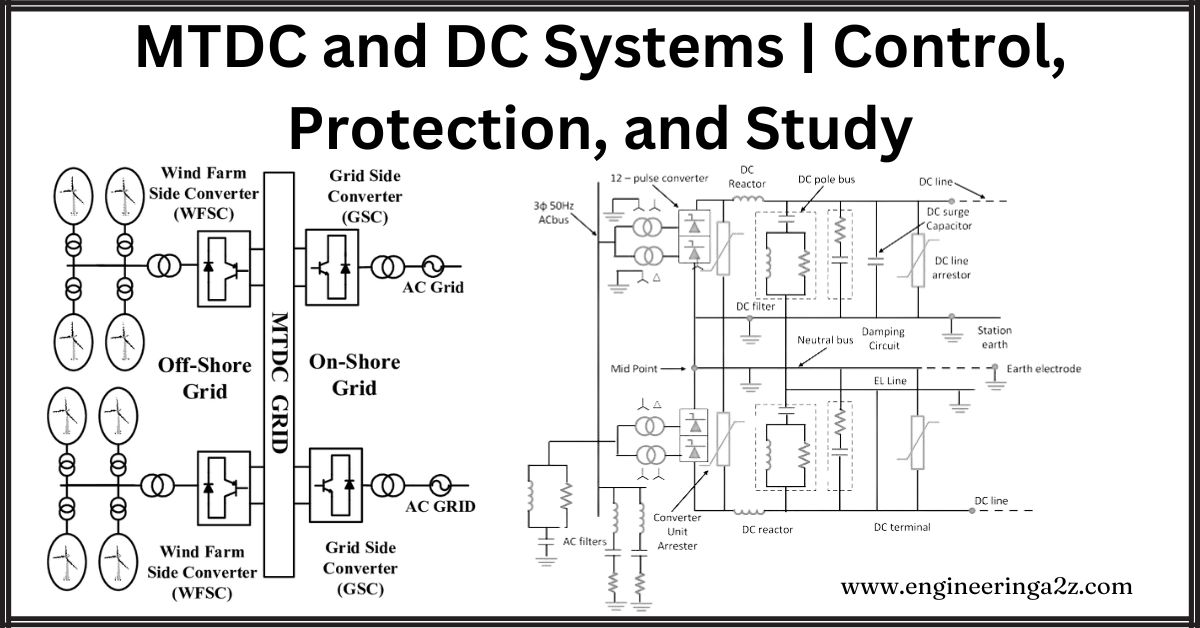
where n is the number of terminals. In the above equation, the inverter currents are treated as negative, while the rectifier currents are treated as positive. The current-controlling terminals operate with a voltage margin that may become zero or negative during disturbances in the AC system As even small disturbances can affect the voltage margin, it is necessary to maintain the current and power distribution in the system with minor changes, during the disturbances. This is possible if current control is also provided at the voltage setting terminal (or slack voltage setting terminal) such that it tries to maintain the same current as before. Because of measurement errors and the requirements of a smooth transition from angle (or voltage) control to current control, the current reference at the voltage setting terminal (VST) is chosen to satisfy the following equation:
Σnj – 1 jref = Imargin
where Imargin is a positive quantity
The converter with the lowest voltage ceiling always acts as a voltage setting terminal The changes in the voltage setting terminal due to disturbances in the AC system are called mode shifts Uncontrolled mode shifts can be minimized by selecting a terminal with the highest short circuit ratio as the voltage setting terminal Due to the negative resistance characteristics of the constant extinction angle control, it would be advisable to choose a rectifier terminal as VST. The magnitude of the current margin is critical as converters of lower ratings can be overloaded when operating at an angle limit.
The central controller that regulates the current orders at all the converter stations is termed a Current Reference Balancer (CRB) and is shown in the analog version in Fig. Here, the current orders calculated from local power controllers are adjusted to satisfy Eq. The limits on the current orders are taken into account in balancing current references. actual implementation of CRB can be performed by using microprocessors.
The Satisfactory operation of MTDC systems requires a reliable central CRB that always operates. This requires reliable two-way communication between a central station and each converter station If there is a loss of a station and this information is not communicated, the system operation is adversely affected. In case of loss of a rectifier station, the power transfer is interrupted by voltage collapse. In case of loss of an inverter station, other stations will be overloaded.
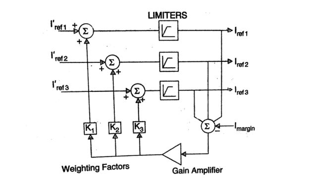
The operation of this control technique is illustrated in Fig. which represents the control characteristics for an MTDC system with two rectifiers and two inverters. When the voltage setting terminal is shifted from INV2 to REC1, the voltage margin AF is added to the reference value at INV2 and subtracted from REC1. The voltage margin control method is also not free from centralized control and fast communication requirements.

To facilitate the operation of MTDC systems even when there is a failure of the communication system, the following modifications to the basic current margin method of control have been suggested:
- Voltage Limiting Control
- Use of Decentralized Current Reference Balancer (DCRB)
- Two ACR (Automatic Current Regulator) methods.
1. Voltage Limiting Control
In the voltage limiting control method, the rectifier and inverter characteristics are arranged as shown in Fig. The loss of a rectifier station does not significantly affect the system operation even in the absence of communication failure. The inverter currents are reduced to prevent voltage collapse. Also, the loss of an inverter station (operating on current control) would not overload the voltage-controlling inverter because of its voltage reserve.

The drawbacks of this scheme are :
- (i) The disturbance in the AC system connected to an inverter station can result in other inverters getting unloaded. (due to a drop in the DC voltage). This may cause adverse effects on the AC systems supplied by healthy inverter stations,
- (ii) Two or more terminals can operate in the voltage controlling mode forcibly, in the case of loss of a terminal resulting in indeterminate distribution of currents in those terminals,
- (iii) Currents during DC line fault or commutation failure are likely to be higher without additional measures
2. Decentralized Current Reference Balancing
This method is similar to the one described by Foerst et al. without CRB and operates on the current and voltage characteristics DCRB is designed to allow rapid recovery of MTDC system operation following severe disturbances that require a momentary rundown of the DC system. The DCRB is supposed to permit the system recovery without coordinated centralized control of converters even if one or more of the terminals is removed from service due to the disturbance.
The operation of the DCRB is illustrated with the help of a 3 terminal system with two rectifiers and one inverter. In the case of the loss of one rectifier station, the characteristics of the remaining two converter stations do not intersect.
The object of the DCRB is to adjust the converter control characteristics around a preselected voltage level Vo in the manner indicated in Fig. The slopes of the balancing characteristics σr and σi determine the relative adjustments that must be made to the current orders. In DCRB, the minimum and maximum current limits are preselected. The intersection of the balancing characteristics determines the steady state operation of the converters following a disturbance The normal post-disturbance characteristics are also shown in Fig. by solid lines. The current order required for this is locally determined by the balanced current and the specified current margin. In the case of a rectifier, a fraction of the current margin would be added to the balanced current, while in the case of an inverter, a fraction of the margin would be subtracted.

The slopes of the balancing characteristics along with the voltage level V0 are chosen, based on the considerations of voltage limits and magnitude of the variations in the DC network voltages during the balancing period. Simulator studies have been carried out to demonstrate the functioning of DCRB and it is claimed that this technique is quite satisfactory in rapid restarting of the system with communication failure.
3. Two ACR Method
In this method, each converter is provided with two automatic current regulators (ACR) and one voltage regulator. The rectifier and inverter control characteristics are shown below.

During the normal mode of operation, the rectifier station with the lowest voltage reference or the inverter station with the highest voltage reference acts as a voltage setting terminal. The remaining converter stations operate under the control of ACR1. Iref1 of the voltage setting terminal is set larger than the operating current (determined by other converters) by the current margin. The ACR2 operates during a contingency and its order can be fixed at the minimum operating current of the inverter.

Without additional measures, the inverter may not be able to recover from a commutation failure. Voltage-dependent current order limit (VDCOL) is introduced to overcome this problem The operation of a 4 terminal system both during normal conditions and when one of the converter stations is shutdown, is shown in Fig.
(The rectifier with the highest voltage order and inverter with the lowest voltage order are always controlled by ACR1, thus resulting in small power deviations during a disturbance) This can be utilized to prevent a shutdown of a base station (such as a nuclear power station) or prevent interruption of supply to a critical AC system.
It is claimed that the two ACR methods permit the use of DC circuit breakers to isolate a line fault or converter fault without coordination with control. The system operation follows a the disturbance is optimized by modifying the current orders from the central controller.
4. Protection of MTDC Systems
One of the issues under discussion regarding MTDC system operation is the evaluation of protection requirements and coordination with control. Conceptually, the system can be shut down following a fault in the DC line or converter station, and the faulted component is isolated using high-speed disconnect switches. The system can be restarted after adequate time for deionization of the arc path in case of short circuits.
System reliability considerations dictate the need for fast clearing of fault with minimum disturbance to the healthy parts of the system The DC breaker ratings can be minimized by utilizing the intervention of fast current controls to reduce the magnitude of the fault currents The detection of DC line faults gets complicated in a mesh system. A major problem is the large drop in the DC voltage even for distance faults. This requires fast detection and clearing of faults to maintain power transfers. Differential types of protection or directional sensitive measurements of the currents can be used to locate the fault. Communication would be required in both methods.
DC switches would be required primarily for parallel MTDC systems and particularly in mesh systems to utilize the improved security provided by such configurations.
Study of MTDC Systems
The planning, design, and operation of MTDC systems require detailed study using simulation tools. The new control and protection concepts have been formulated using HVDC simulators. The performance of the controllers is judged not only under normal conditions with changing load conditions but also under disturbances caused by faults in the AC system and DC lines. Some of the typical problems that have been considered for study are as follows:
- Operation of small inverter taps connected to weak AC systems
- Integration of existing HVDC converter stations in MTDC systems without major modifications in control
- Evaluation of communication, reactive power, and filtering requirements
- Security of power transfer without fast communication links
- Power and reactive power modulation strategies in MTDC systems.
Some of the conclusions from studies carried out indicate the type of problems that can be anticipated in the operation of MTDC systems connected to weak AC systems.
- A large smoothing reactor may be required to help in the recovery of a small inverter from AC faults.
- The speed of recovery of the entire MTDC system depends upon the recovery of the small tap if it is still connected to the system following clearance of a fault.
- It is necessary to consider the effect of mode shifts and develop additional protection sequences, particularly for faults in the DC line.
- The provision of VDCOL at each rectifier is beneficial and its characteristics have to be adjusted suitably.
With a good knowledge of HVDC controls and their accurate modeling, HVDC simulators (both physical and digital) can be used to analyze problems and search for solutions. For example, during the tests for parallel operation of the two bipoles in the Nelson River HVDC transmission system in Manitoba, Canada, in 1985, it was observed that there was a current oscillation of 6 Hz in the two inverters although the current in the two rectifiers was steady. The Vd – Id characteristics for the rectifiers and the inverters are shown in Fig. (a) and (b) respectively. The operating voltage is also shown here, which indicates that the inverter 2 operates in the mode of current error-dependent gama control mode. In simulating the system using the EMTDC program with generic modeling of the controls, it was not possible to identify the source of the (oscillation) problem. However, from the knowledge of the actual valve group controller (provided by the manufacturer) it was possible to identify the source of the problem to a particular K / (1 + sT) type delay block in the actual controller. By decreasing the time constant 7 from 22 ms to 3 ms, it was possible to eliminate the current oscillation problem in the real system. Incidentally, the digital program also allows one to experiment and determine how the oscillations are initiated from a stable operating point. In this case, changing the tap ratios from the set point initiated the low-frequency current oscillations.
An HVDC simulator study of a four-terminal MTDC system indicated the possibility of adverse interaction between the control and DC network dynamics. This can result in multiple mode shifts in rectifiers following a remote three-phase fault at a rectifier. A commutation failure at the small inverter results in the total DC (from the rectifiers) being diverted into the faulted inverter due to a voltage drop in the inverter caused by the commutation failure. The transient current is even higher due to the discharge of line capacitances. The peak current can be limited partly by the use of a higher smoothing reactor. However, it is difficult for the inverter to recover even when the AC system is strong. The system recovery is made possible by initiating Force-Retard (FR) on the rectifiers (increasing a to values above 90°, say 145°) as done in the case of DC line faults in a two-terminal system. FR can be initiated without tele- communications since the collapse of the DC voltages at the rectifiers can be used as signals for the protective action. After a pre-determined time, the converter firing angles are returned to their normal values at a controlled speed. However, there is still a danger of a subsequent commutation failure at the small inverter due to current overshoots. The characteristics of a VDCOL at the inverter have to be carefully chosen to avoid this problem.
Multi -Infeed DC Systems
Although multiterminal DC systems are not yet common, more than one HVDC link may feed into the same load area. In reference, an attempt was made to answer the question of possible limits of HVDC power supplied to an AC system. The author identified two major issues that can affect the limits-(i) current harmonics injected by the converter and (ii) compensation of reactive power. The first issue is closely connected with the generation of non-characteristic harmonics and the possibility of harmonic instability (which is essentially the phenomenon that results in sustained non-characteristic harmonics due to AC-DC system interactions). According to this, this is mainly dependent on the frequency dependence of the AC system (including the AC filters) impedance viewed from the converter terminals and not necessarily dependent on the Short Circuit Ratio (SCR). Harmonic instability can occur even at higher SCR. Incidentally, there was also a belief earlier that the problem of harmonic instability was completely solved after the development of the Equidistant Pulse Control (EPC) scheme of firing pulse generation. However, this assumption is also not valid. There could be adverse harmonic interactions even with EPC.
The second issue of reactive power compensation is related to the problem of voltage instability and voltage flicker (caused by switching a filter or capacitor bank). This is primarily dependent on the SCR and the problem can be aggravated at low SCR. There is also the problem of overvoltages caused by load rejection which can be tackled by applying SVC or STATCOM for reactive power compensation.
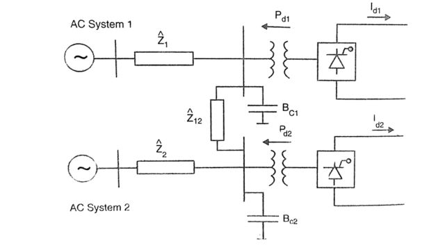
References formulate the problem of MIDC systems by considering the system shown in Fig. The AC system shows an equivalent circuit based on Thevenin impedances.
The interaction between the two HVDC converters that may belong to two different HVDC links can be ignored if the impedance Z12 is large compared to Z1 or Z2. Thus, in a large network with several embedded DC links, the DC control design can be made based exclusively on SCR at the AC connection point, without considering the other DC links, if the transfer impedances between the commutation busbars are high.
The control strategies at the rectifier and the inverter have a bearing on the voltage stability of the system. Current control rather than power control at the rectifier improves matters while constant DC voltage control at the inverter is much better than constant extinction angle control.
The interactions among inverters nearby require a coordinated design of controllers. The voltage distortions caused by persistent commutation failures in one inverter, also affect the other inverter. The VDCOL characteristics of one inverter that decide the speed of recovery following DC faults can affect the voltage at the inverter.
The control and protection in MIDC systems must be carefully designed to avoid adverse interactions. Interestingly, a BTB link interconnecting two asynchronous AC systems can introduce low-frequency current oscillations in a nearby rectifier. For example, even if the nominal frequencies of the AC systems interconnected by a BTB link are the same, there can be variations in the frequencies. If one frequency is 50 Hz while the other is 49 Hz, the DC link with 12 pulse converters will have voltages of frequencies 600 Hz and 588 Hz. This can result in the AC bus voltages having a 12 Hz frequency component and the current controller in the rectifier in proximity can react to this. Such oscillations have been observed in HVDC simulator studies.
MTDC Systems Using Voltage Source Converters
The VSC-based HVDC transmission is ideally suited for multiterminal operation due to the following advantages:
- (1) The power reversal in a converter is achieved by current reversal which is easily arranged by control action without having to use mechanical switches to reverse the polarity of the converter connections to the conductor in a parallel MTDC system. In line commutated converters, the power reversal requires voltage reversal and this implies that the converter has to be connected to the conductor of the opposite polarity.
- (2) There is no problem of commutation failures in an inverter based on VSC. A VSC-based inverter can even supply passive loads.
- (3) The use of Pulse Width Modulation (PWM) eliminates low-frequency harmonies and simple AC filters can be supplied.
- (4) There is no need for reactive power compensation of VSC. A VSC can supply reactive power and can help in the control of the AC voltage.
However, it is to be noted that harmonic interactions can occur in VSC also and the choice of the circuit parameters and control design must consider this problem. However, the problem is likely to be less complicated compared to LCC.
One of the drawbacks of VSC is the problem of handling DC faults. Since DC capacitors can discharge into the fault, the protection must disconnect the converter from the line or block the firing pulses to the converter and trip the converter. In the case of the LCC rectifier, the action of forced retard (FR) can help in clearing the fault by deionization of the fault arc. This difference in the action of LCC and VSC rectifiers has prompted the application of hybrid MTDC schemes, with LCC rectifiers and VSC inverters. Of course, when a terminal has to operate in either of the two (rectifier or inverter), obviously VSC is the choice.
Note that in the case of cable transmission, the probability of DC faults is less (although any cable fault can be non-self-healing).
In urban areas, importing from distant generators generally meets the increasing power demand. The application of DC transmission has the advantage of not contributing to short circuit levels (the increase in short circuit levels would require upgrading switchgear ratings). Thus, the introduction of MTDC systems based on VSC in urban areas is quite attractive
Frequently Asked Questions (FAQs)
-
What is the MTDC system in HVDC?
The MTDC (Multi-Terminal Direct Current) system in HVDC (High Voltage Direct Current) allows multiple points to connect to a DC transmission line, enabling efficient power transfer over long distances with varying sources and destinations.
-
What is the introduction of MTDC?
The introduction of MTDC (Multi-Terminal Direct Current) systems expanded HVDC technology by enabling multiple connection points to a single DC transmission line, enhancing flexibility and efficiency in power transmission networks.
-
What are the DC links in HVDC?
DC links in HVDC (High Voltage Direct Current) systems are transmission lines that carry direct current (DC) electricity between converter stations, facilitating long-distance power transmission with minimal losses.
-
What is the application of a DC transmission system in HVDC?
HVDC (High Voltage Direct Current) transmission systems find application in long-distance power transmission, submarine cable connections, interconnecting asynchronous AC grids, and facilitating efficient integration of renewable energy sources.
Read Also:
- Comparators | Definition, Types of Comparators
- DC Breakers | Characteristics, Types, and Applications
- MTDC | Introduction, Potential Applications, and Types
- Static Relays I Basis, Classification, and Components


Leave a Reply