
Table of Contents
Criteria of Design
The major design objective of AC filters is to reduce telephone interference. Any of the following performance indices can measure this.
Harmonic Distortion
This can be measured in two ways:
D = (Σmn = 2 In Zn / E1) . 100
in percentage where I, Z, and E, are the harmonic current injected, the harmonic impedance of the system, and the fundamental component of the line to neutral voltage respectively. m is the highest harmonic considered (49 or 50). The second definition is
D = ([Σmn = 2 (In Zn)2]1/2 / E1) . 100
In some cases, the harmonic distortion can be defined individually for a single harmonic as
Dn = (InZn / E)×100
Telephone Influence Factor
This is an index of possible telephone interference and is defined as
D = ([Σmn = 1 (In ZnFn)2]1/2 / E)
where
Fn = 5nf1pn
pn is the C message weighting used by Bell Telephone Systems (BTS) and Edison Electric Institute (EEI) in the USA. This weighting reflects the frequency-dependent sensitivity of the human ear and has a maximum value of 1.0 at 1000 Hz.
Telephone Harmonic Form Factor (THFF)
This is analogous to TIF except that
Fn = (nf1 / 800)Wn
where W, is the psychometric weight at the harmonic order n, as defined by the Consultative Commission on Telephone and Telegraph Systems (CCITT), While TIF is used in the USA, THFF is popular in Europe. The maximum value of W, 1.0, at 800 Hz.
IT Product
In the BTS-EEI system, there is another index called IT product which is defined by
IT = [Σmn = 1 (In Fn)2]1/2
KIT product is defined as
KIT = IT / 1000
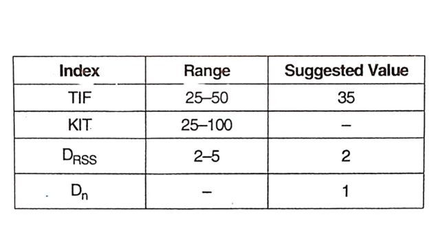
Although there are no specific standards for the performance requirements, the suggested values of the above indices are given in Table.
Types of Filters
Two types of filters can be used. These are (1) Passive filters and (2) Active filters. The passive filters can be further divided into (a) tuned (high Q) filters and (b) damped (low Q) filters.
The passive filters have been used in the HVDC converter station right from the beginning and continue to be used. Tuned filters are used to filter out individual harmonics – both characteristic and non-characteristic. For example, in present-day twelve pulse converter stations, tuned AC filters are used for 11th and 13th harmonics in addition to say 3rd harmonic which may be problematic (particularly if the DC circuit has a resonant frequency corresponding to the second harmonic).
The requirement of AC and DC filters with overhead DC lines adds to the cost of converter stations. However, in the case of AC filters, passive filters act as sources of reactive power required for the Line Commutated Converters (LCC) with thyristor valves. The DC side’s smoothing reactors contribute to DC harmonics’ filtering. Back-to-back (BTB) HVDC links are not provided with DC filters as they are not required. DC filters are designed to minimize primarily telephone interference in the wire-line communication circuits in the vicinity and costs associated with these filters can be avoided if there are no interference problems.
However, with overhead lines, the interference from the DC harmonics can be critical. Active filters (based on VSC) in series with the passive filters have been suggested to save costs associated with filtering. Although active filters are costly, there are several advantages over passive filters, and a hybrid solution is generally preferred if the performance of filters is to be improved. With AC filters, the active filters are not yet cost-advantageous unless the reactive power requirements at the converter station are minimal (for example, in the case of capacitor-commutated converters).
Passive AC Filters
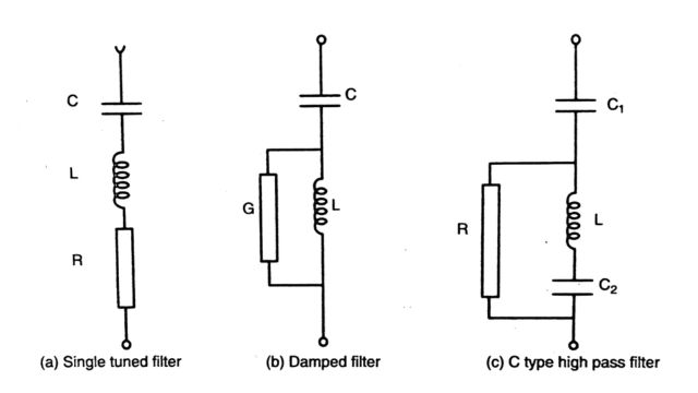
A single-tuned filter and a damped filter are shown in Fig. (a) and (b) respectively. For both these filters, we define ωr = 1 / √LC as the resonance frequency and X0 = ωrL = 1 / ωrC = √LC as
the reactance of the inductor or capacitor at the resonance frequency. Note that both filters become identical when R = G = 0 In this case the impedance of the filter is purely reactive and becomes zero at h=hr where hr, is the order of the harmonic for which the filter is designed. We express the sharpness of tuning in terms of the quality factor (Q) defined as
Q = X0 / R for the tuned filter
Q = 1 / GX0 for the damped filter
Note that G is the conductance of the resistor in parallel with the inductor for the damped filter
The Impedance of Single-Tuned Filter
The impedance (Z ph ) of the single-tuned filter at the harmonic order ‘h’ is given by
ZFH = R + j (hωL- 1 / hωL)
where ω is the fundamental frequency which can vary with the power system operating conditions.
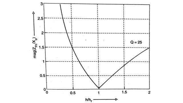
A tuned filter is designed to filter a single harmonic (of order h,). If hrω then obviously ZFH = R= X0 / Q and is minimum. The variation of ZFH / X0 as a function of h / hr is shown in Fig.
Here, h is viewed as a continuous variable. Since o is variable and there could be errors in the tuning ( ωr ≠ hrωn where ωn is the nominal (rated) system frequency), it is necessary to compute the impedance of the tuned filter as a function of the detuning parameter (δ) defined by
δ = hrω – ωr / hrωn = ω / ωn – ωr / hrωn
Considering variations in the frequency (f), inductance (L), and capacitance (C), we can express δ as
δ = 1 + Δf / Δn – [ (1 + ΔL / Ln) ( 1 + ΔC / Cn) ]-1/2
δ = Δf / fn + 1 / 2 . ΔL / Ln + 1 / 2. ΔC / Cn
where Ln and Cn are the nominal values of L and C such that hrωn = (hnCn)– 1/2
It is to be noted that AL can be treated as the error in setting the value of L. The variation in C can be due to (i) an error in the initial setting of C and (ii) the variation in C due to the temperature dependence of the dielectric constant. We can express ZFH as
ZFH = R + jX0 [ ω / ωn . L / Ln – ωn / ω. Cn / C ]
X0 = hrωnLn = 1 / hrωnCn
The quantity inside the brackets in the RHS of Eq. can be expressed as
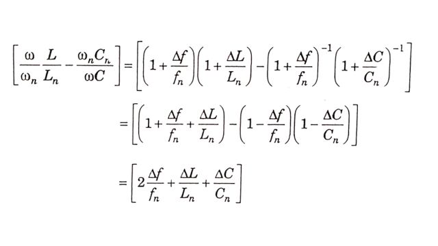
From Eq. is equal to 2δ. Thus, we can finally derive,
ZFH = R+jX0 . 2δ = X0 ( Q-1 +j2δ) where Q is defined in Eq.
Impedance of Damped Filter
The tuning in a damped filter is not critical, hence we will ignore the effects of variations in the system frequency (ω) impedance (L), and capacitance (C),
Defining ω = 1 / √LC = h0ω, Q = R / X0, X = h0ωL = 1 / h0ωC
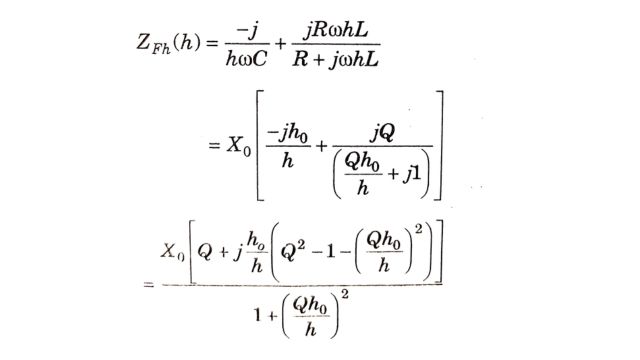
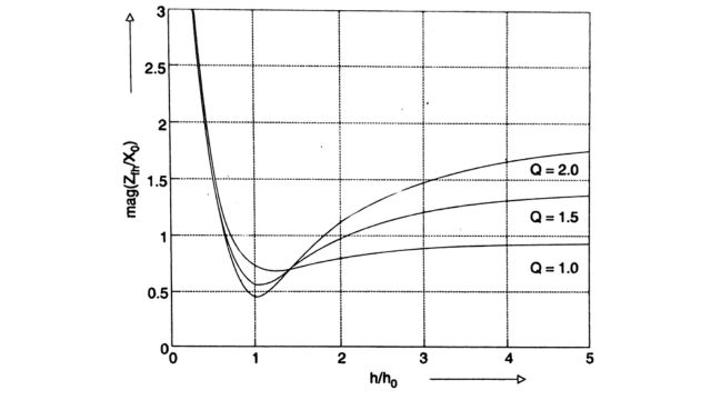
The variation in the (normalized) magnitude of the damped filter ( ZFh / X0) as a function of high is shown in Fig. for three different values of the quality factor Q. It is observed that the impedance remains practically constant at higher frequencies.
A damped filter is used in converter stations as a second-order high-pass filter to filter out higher-order harmonics. The tuning of these filters is not critical. The losses at the fundamental frequency can be reduced by using a C-type filter where the capacitor C, in series with L, provides a low impedance path to the fundamental component of current.
A typical converter station with 12 pulse converters has double-tuned (or two single-tuned) filter banks to filter out 11th and 13th harmonies and a high pass filter bank to filter out the rest of the harmonics. Sometimes a third harmonic filter may be included to filter out the non-characteristic harmonic of the third order (particularly with weak AC systems where some voltage unbalance is expected). All the filter branches appear capacitive at the fundamental frequency and supply reactive power.
Automatic Tuning of Filters
The optimum value of the quality factor of tuned filters is inversely proportional to δm which primarily depends on the frequency deviations in the system). The low Q (quality factor) results in increased losses and increased harmonic distortion at the converter bus. To maintain the same level of filtering, the value of the capacitance has to be raised increasing the cost. The only advantage of low Q is the reduction in the harmonic currents in the filters caused by ambient harmonics (sources other than the HVDC converters).
The automatic tuning was tried earlier by varying the inductance of the filter by the use of a tapped coil with a tap-changing mechanism or by a variometer (a fixed coil in series with a movable coil so that the coupling between the two coils is variable). The controller works to reduce the phase angle between the harmonic voltage and the current.
Recently ABB has developed Continuously Tuned (ConTune) AC filters (for single-tuned filters) by variation of the inductance of the filter reactor without moving parts. The variable inductance is achieved with an iron core placed inside the reactor. Around the iron core is wound a control winding in which a variable DC can flow. The principle of this method is based on the variation of permeability of the magnetic material by applying a transverse magnetic field (perpendicular to the main flux direction). As the current increases from zero, the inductance decreases continuously. The controller uses a P-I regulator and a 6-pulse controlled rectifies (as an amplifier)
A test installation of an 11th harmonic ConTune filter was made in the Lindome Station of the 300 MW Konti-Skan 2 HVDC link in 1993. The filter generates a reactive power of 11.6 MVAR at 132 kV. The filters were designed to accommodate frequency and component variations that represent detuning of -3 to 2 Hz. The ConTune filter had a Q factor of 200 and resulted in a substantial reduction in the 11th harmonic distortion. A commercial installation of the ConTune filter was subsequently done at the Celilo terminal of the Pacific Intertie HVDC link in the western USA.
Design of Combined AC Filters
While Eq. can be used for finding the optimum Q factor of each tuned branch, the harmonic voltages have to be computed by considering the entire filter as a unit. Accurate computation of the harmonic voltages requires a good knowledge of the harmonic characteristics of the AC system. This is best done by using digital computer programs
The size of individual filter branches has to be determined by the considerations of (i) demands on the reactive power at various loading conditions and how they are to be met and (ii) the filtering considerations of satisfying constraints on telephone interference. The optimization of filter design involves several trials by checking various combinations (of filter branches and shunt capacitors/reactors) and operating conditions that also affect the AC system harmonic characteristics.
Ratings of Filter Components
The voltage and current stresses of AC filters consist of the fundamental frequency and harmonic frequency components. Their magnitudes in steady-state depend on the AC system voltage. harmonic currents generated by the converters and AC system impedances. It is necessary to determine the highest steady-state current and voltages for each filter component, based on calculations performed over the entire operating range.
The study of transient voltage and current stresses enables the computation of the energy duty of filter resistors and arresters in addition to the insulation levels for all the filter components. To calculate the highest stresses, the following cases are investigated.
- (1) Single-phase ground fault: The fault is applied on the converter bus next to the AC filter. It is assumed that the filter capacitor is charged to a voltage level corresponding to the switching impulse protective level of the AC bus arrester.
- (2) Switching surge: For the calculation of the switching surge stresses, a standard wave of 250/2500 us with a switching impulse protection level of the AC bus arrester is applied at the converter bus.
- (3) Filter energization: To determine the maximum inrush currents for AC filters, they are energized at the instant of the (maximum) AC peak voltage at the filter bus.
- (4) Fault recovery after three-phase ground fault: To determine the maximum energy stresses for the filter arresters and resistors, various fault-clearing scenarios are considered. Worst-case stresses occur if the HVDC converter is blocked after fault initiation, while AC filters remain connected to the AC bus after fault clearing and recovery of the AC System voltage. In this case, load rejection by blocking the HVDC converters results in temporary overvoltages with a high content of non-characteristic harmonics due to transformer saturation and low harmonic resonances between the filter and AC network.
Protection of Filters
The filter is exposed to an overvoltage during switching in and the magnitude of this overvoltage is a function of the short circuit ratio (higher with low values of SCR) and the saturation characteristics of the converter transformer. During switching in, the filter currents (at filter frequencies) can have magnitudes ranging from 20 to 100 times the harmonic currents in normal (steady-state) operation. The lower values are for tuned filters and higher values apply to high-pass filters. These overcurrents must be taken into consideration in the mechanical design of reactor coils.
When filters are disconnected, their capacitors remain charged to the voltage at the instant of switching. The residual direct voltages can also occur on bus bars. To avoid this, the capacitors may be discharged by short-circuiting devices through converter transformers, or by voltage transformers loaded with resistors.
If the network frequency deviates from the nominal valve, higher currents, and losses will result in AC filters. If they exceed the limits, the filters have to be disconnected.
Frequently Asked Questions (FAQs)
-
What is the AC and DC filter?
AC filters remove unwanted frequencies from alternating current signals, smoothing out voltage fluctuations. DC filters eliminate noise and ripple from direct current signals, ensuring a steady and clean power supply for electronic devices.
-
What is the protection of a filter in HVDC?
Protection of HVDC filters involves measures to safeguard against overvoltage, overcurrent, and overheating, ensuring the reliability and integrity of the high-voltage direct current transmission system.
-
What is the use of a filter in a DC power supply?
In a DC power supply, filters are used to remove unwanted AC components or noise from the output voltage, ensuring a stable and smooth DC output suitable for electronic devices.
Read Also:
- DC Filters | Criteria, Carrier Frequency, and RI Noise
- DC Breakers | Characteristics, Types, and Applications
- Comparators | Definition, Types of Comparators
- Smoothing Reactor and DC Line | Transient overvoltages, Protection, and Effects


Leave a Reply