Table of Contents
Introduction
The smoothing reactor is connected before the DC filter and in series with the converters. Apart from smoothing the direct current, it also serves as a buffer between the converters and the DC line. The sizing of the reactor depends on various requirements including the reduction of ripple in the current.
The DC line, in the case of a bipolar system, consists of two conductors, one operating at positive polarity (concerning the ground) and the other at negative polarity. Extra high voltage DC lines have bundled conductors to minimize the effects of corona. The design of a DC line is carried out with similar considerations as an AC line. However, the performance of insulators is different with direct voltage and the problems of pollution are severe compared to AC operation. However, the converter control allows reduced voltage operation under heavily polluted conditions.
The protection against faults in a DC line is invariably through the converter control. This is mainly due to the non-availability of DC breakers in the early stages of the introduction of HVDC systems. However, the reliability of converter control has led to its continued use even when DC breakers have been developed. The DC breakers may be required under special operating requirements such as transfer from ground to metallic return and multiterminal system operation.
The corona effects, overvoltages, insulation, and protection against faults are some of the aspects that will be discussed in this chapter. Some aspects of the metallic return and the operation of AC and DC lines in the same right of way will also be considered.
Smoothing Reactor
The smoothing reactors have several functions as given below:
- They reduce the incidence of commutation failure in inverters caused by dips in the AC voltage at the converter bus.
- They prevent consequent commutation failures in inverters by reducing the rate of rise of direct current in the bridge when t’ the direct voltage of another series connected bridge collapses.
- They smooth the ripple in the direct current to prevent the current from becoming discontinuous at light loads.
- They decrease harmonic voltages and currents in the DC line.
- They limit the crest current in the rectifier due to a short circuit on the DC line.
- They limit the current in the valves during the converter bypass pair operation, due to the discharge of shunt capacitances of the DC line.
- It is to be noted that in back-to-back HVDC systems, the last three functions are not relevant. For systems with DC transmission lines, the inductors of value from 0.27H to 1.5H have been used. For back-to-back HVDC systems, the value ranges from 12 mH to 200 mH.
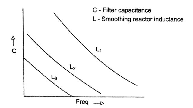
- The sizing of the reactor is done not only from the considerations mentioned above but also from the point of view of minimizing the effect of low-order harmonic resonances in the AC/ DC system. It is necessary to avoid series resonance of the DC system at the fundamental frequency and also at the second harmonic. The effect of the inductor value on the resonant frequency (corresponding to the first peak of the admittance as seen by the converter) as a function of the DC filter capacitance is shown in Fig. Here, L3 > L2 > L1 shows that the resonant frequency is reduced by increasing the inductance.
The inductance value must remain practically constant with variations in the direct current. This requires air-core construction. The smoothing reactor helps to limit the fault current in the DC line as mentioned above. This is feasible only if the reactor does not get saturated by the fault current. By the way, it is to be noted that saturable reactors used for the limitation of dildt in thyristor valves, cannot replace the smoothing reactor as smoothing reactors unaffected by saturation reduce commutation failures.
The location of the smoothing reactor can be either at the high voltage terminal or at the ground terminal as shown in Figs. (a) and (b) respectively. In the latter case, it is also necessary to have a small reactor of the order of 5 to 10 mH on the line side, to protect the converter station from the consequences of lightning strokes to the line. The advantage of having the reactor on the ground side is that it allows the converter ground faults to be cleared by converter control (increasing the delay angle to its maximum limit to control the current). The insulation level of the reactor is reduced for this location of the reactor.

There is little information available on the choice of the optimum size of the DC smoothing reactor. One criterion used is the S, factor [1,2] defined below
Si =Vdn / (LIdn )
where Vdn and Idn are the rated direct voltage (in kV) and direct current (in kA) respectively. L is the DC circuit inductance in mH which includes the transformer leakage inductance. The Si factor for back-to-back HVDC links varies from 0.24 to 1.3ms-1. The higher the factor, the higher the rate of rise of the fault current.
The alternate criterion for the sizing of the reactor is the ripple in the direct current. For a converter feeding a constant voltage source through a constant inductor (see Fig.), the peak value of the ripple is given by
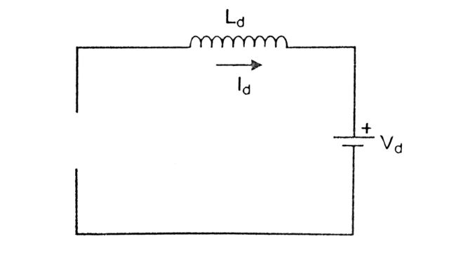
idpeak = (s Vdo / ω1 Ld) [ 1- ( π / p) cot( π / p)] sin a
where Vdo is the no-load DC voltage of a converter, s is the number of converters connected in series, p is the pulse number, Ld is the inductance of the reactor, ω1 is the fundamental frequency. In deriving Eq., the leakage reactances of the converter transformers are neglected. A major assumption used in deriving Eq. is that the delay angle a exceeds ā
where tan ā = (p / π) – cot(π / p)
for p = 6, ā = 10° and for p=12, ā = 5°
In the former case
idpeak = 0.0931(s Vdo ) sina /( ω1 Ld)
while for p = 12
idpeak = 0.0230(s Vdo ) sina /( ω1 Ld)
For the case where a = 0
idpeak = k(s Vdo ) / ( ω1 Ld)
where the constant k = 0.00947 for p = 6 and k = 0.00119 for p = 12
It is necessary to avoid discontinuous conduction of current in the converter valves during the system operation. This is because of the possibility of overvoltage across the valves that are transmitted from the line side.
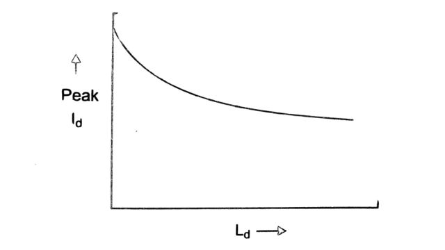
Another factor that could affect the sizing of the smoothing reactor is the peak direct current during the bypass pair operation caused by commutation failures. The figure shows the effect of the smoothing reactor inductance. This shows that the reduction in the surge current is not commensurate with the increase in Ld beyond a certain point.
DC Line
1. Corona Effects
The corona is defined as a ‘luminous discharge due to the ionization of air surrounding a conductor caused by a voltage gradient exceeding a certain value’. The ionization takes place in a zone which is a very thin circumferential layer (not more than 2 cm) surrounding the conductor surface. Within this zone, the high field strength causes high-velocity particles to collide with the air molecules. Electrons are removed from the atoms of the air molecules and are accelerated towards the positive conductor or away from the negative conductor. These high-velocity electrons collide with other air molecules releasing additional electrons in an avalanche process. The ions carrying the same charge as the adjacent conductor are repelled from the ionization zone at initial velocities of about 1.4 cm/sec for positive ions and 1.6 cm/sec for negative ions for every V/cm of the field strength.
The ions moving into the inter-electrode region (between pole to pole or between pole to the ground) recombine with oppositely charged ions or neutral molecules. To maintain the net charge in this region, a corona current flows from the conductor by the movement of electrons in the ionization zone and by ions beyond this zone.
The ions velocities at the ground level are in the range of 3 m/sec for typical voltage gradients. The ion movement in perfectly still air conditions is restricted to the electric field direction. However, with wind movement, the ions are randomly dispersed downwind from the DC line. The losses are also increased.
The effects of the corona are:
- Corona loss
- Radio and television interference
- Audible noise
- Space charge field
While the first three effects occur on AC lines also, the last one is peculiar to DC lines. It involves the effect of movement of ions which results in the increase in the voltage gradient at the ground level. The ‘electrostatic field’ is defined as the field resulting from the charges on or near the conductor surface. The total ‘electric field’ results from the superposition of the electrostatic and space charge fields.
(a) Corona loss
The power losses due to corona can be expressed as:
Ploss = [ 2V (k+1) kcnr20.25(g-g0)]x10-3 kW/circuit – km
where
- V is the pole-to-ground voltage in kV
- n is the number of subconductors
- r is the radius of each subconductor in em
- g = maximum conductor surface gradient at operating voltage (in kV/cm)
- g=228 kV/cm where 8 relative air density
- k = conductor surface coefficient which varies from less than 0.15 for smooth, clean conductors to more than 0.35 for conductors with imperfections
- k = (2/n) tan-1 (2H/S)
- H mean height of conductors
- S = pole spacing
The relative air density & is given by
82.94p/(273+T)
where
- p = barometric pressure in kilo-Pascals
- T=temperature in centigrade
Morris and Maruvada have applied the Mangolt equation to the calculation of conductor surface gradients for bipolar lines. The maximum gradient g, is given by

where R = radius of the circle passing through the centres of all subconductors in a bundle, in cm. The other quantities are as defined earlier. It refers to the natural logarithm. The power loss predicted by Eq. gives correctly the mean fair-weather corona loss level With rain, the DC losses may increase by a factor of 10 to 1 while AC losses may increase by 50 to 1. However, the average ratio of rain weather loss to fair weather loss varies from 2 to 4 with higher ratios applicable to operation at lower gradients.
The bipolar corona loss per pole is higher than the monopolar corona loss by a factor of 1.5 to 2.5. However, for a given voltage, the positive and negative polarity losses are approximately equal. DC corona losses usually increase with wind velocity in the range of 0 to 10 m/sec.
(b) Radio Interference (RI)
The most predominant corona effect that may determine the conductor design is the ratio interference. This is measured at a frequency of 1 MHz and for a receiver bandwidth of 9 kHz, at a horizontal distance of 30 meters from the outermost conductor.
The RI is mainly due to the positive conductor. This is because the corona discharges from the negative conductor are in the form of Trichel pulses which are uniformly distributed over the conductor surface. Positive corona discharges are of three types glow, plume discharge, and streamers, Plumes and streamers are randomly distributed and the more persistent discharges are usually associated with high-stress points due to surface imperfections. These are mainly responsible for the RI.
The expression for RI (in decibels above the field strength of 1 µV per meter) is empirically obtained as
RI = 25 + 10 logn + 20 logr + 1.5(g-go)
This is due to the positive conductor. The RI due to the negative conductor is about 20 dB lower and is not of consequence.
Interestingly, DC-RI levels are decreased by rain and wet snow which completely wet the conductor. This phenomenon is opposite to that in AC conductors.
DC-RI levels are increased by wind, with maximum increase during the wind flow from negative to positive conductor.
The bipolar lateral RI profile is symmetric about the positive pole and attenuates inversely as the square of the distance from the conductor initially (up to 50 meters) and inversely as the distance thereafter.
The television interference (TVI) with DC lines is mainly due to the ion currents and is of little consequence at distances greater than 25 meters from the right of way.
(c) Audible noise (AN)
The corona discharges from the conductor produce compressions and rarefactions that are propagated through the medium as acoustical energy. The portion of the acoustical energy spectrum that lies within the sonic range is perceived as audible noise (AN).
The sound level is expressed in decibels and is defined as
dB = 20 log(P/PR)
where P is the measured sound-pressure level and PR is the reference pressure level. The standard level for PR is 20µ Pascal which is the average threshold of audio perception at 1 kHz. Test line studies indicate that ± 600 kV DC lines would produce an audible noise of 45 to 55 dB measured at 30 meters from the ROW center line. This is not considered to be serious. In general, the annoyance produced by the audible noise varies linearly with the conductor surface voltage gradient.
The test results also show that a positive polarity conductor is the primary source of AN. Rain causes a very slight reduction of AN.
Audible noise is produced in converter stations by converter transformers and smoothing reactors due to the phenomenon of magnetostriction. Although higher AN is to be expected in converter transformers (compared to transformers in AC substations) due to the presence of harmonics, this is counterbalanced by the operation at lower flux densities in the core. Audible noise has not been a serious problem in converter stations.
(d) Space charge (lon flow) field
As mentioned earlier, the ions produced by the corona on overhead DC lines drift through space under the action of electric field and wind. The possible environmental effects due to electric fields and space charges, particularly at the ground level are matters of concern and have to be considered in transmission planning.
In AC lines, the problem of ion flows is not present as all the ions created during the one-half cycle are recaptured during the second half-cycle by the polarity reversal on the conductor. The net effect is the increase in the diameter of the ionization zone as the surface gradient increases above the critical level. Very few ions escape the ionization zone.
Although ion flow fields are absent around AC lines, the time-varying field can induce currents in humans or objects due to capacitive coupling. Experimental studies have shown that the magnitudes of these induced currents can be about 100 µA for a person directly under a typical EHV or UHV line. Such capacitive coupling effects are not present with DC fields. The current induced under DC fields is due to the flow of ions. The current density (in Amps/meter) can be obtained from the relationship
j = kpE
where
- k = ion mobility (1.8 x 10⁻³ m/s/v/m for negative ions)
- p = charge density in coulombs/m³
- E = electric field strength in volts per meter.
The charge density at ground level can be calculated from
p=εΔE
where & is the electric permittivity.
The total current intercepted by a person at ground level is the current density multiplied
by the equivalent area which is related to the height. For a person of height 1.73 meters, the maximum current intercepted is around 3 µA under a line operating at ±600 kV. Incidentally, the threshold of perception level for direct currents is 5.2 mA for men and 3.5 mA for women, These levels are higher than the threshold levels for AC currents.
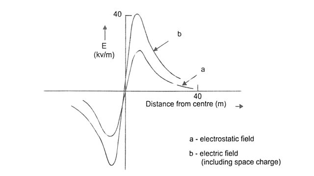
The total electric field at the ground level is a superposition of the space charge field and the electrostatic field. The lateral ground level profiles of the electrostatic and electric fields are shown in Fig.
The computation of ion flow fields is complex as non-linear partial differential equations are involved. The computations are simplified by Deutsch’s major assumption that the space charge affects only the magnitude and not the direction of the electric field. This reduces the two-dimensional ion field problem to a one-dimensional problem. Recent research efforts are directed at improving the accuracy of computations without Deutsch’s assumption, thus allowing the consideration of the effects of wind velocity.
2. DC Line Insulators
The insulator strings of a DC line are made up of porcelain or toughened glass as in the case of AC lines. The insulator performance is evaluated in terms of critical flashover voltage (CFO) and critical withstand voltage (CWS). The critical flashover voltage is defined as the statistical mean (with 50% probability) of a data group (usually 20 flashovers) on a specific insulator specimen. The analysis assumes Gaussian distribution.
The critical withstand voltage (CWS) is defined as
CWS = CFO – 30
where o is the standard deviation. The CWS represents a voltage level with a 0.13% probability of flashover.
It is to be noted that the overvoltage should result only in flashover and not puncture of the insulators.
There are special problems with direct voltage stresses on an insulator. The first problem is that of ion migration that takes place in the insulating material, which is a function of the temperature. An insulating material should have very little ion migration even at high ambient temperatures. There can be thermal runaway due to the ionic conduction in a very narrow zone of the dielectric which results in ageing of the dielectric. The current that flows in the insulator body is dependent on the resistivity which is a function of the temperature.
There is also the phenomenon of electrolytic process due to the creepage currents along the surface of the insulator These currents cause the electrodes to increase in volume, partly through the deposition of material and partly as a result of chemical processes. The insulator design must take this into account to avoid mechanical failures.
The insulator string is subjected to the direct voltage in addition to transient impulses of different waveforms. The creepage distance of an insulator is determined by the operating direct voltage, while the string length is determined by the impulse voltage level. Increasing the string length influences the height of the towers and their costs.
As transient overvoltages are smaller with DC lines (as compared to AC lines), there is an economic incentive to make the ratio of creepage distance to string lengths as great as possible.
A major problem with DC insulators is that the accumulation of contamination through direct voltage stresses is higher than with AC lines. The collection of dirt particles is also less uniform than with AC. Providing collector rings close to the ends of the string helps make the field distribution more uniform and reduces the accumulation of contamination.
The insulators are cleaned by heavy rain while the fog or dew, which makes the dirt conductive without removing it, can result in flashover. At times of unfavorable weather conditions, it may be desirable to operate the DC line at lower voltages by converter control or by removing some of the series-connected bridges.
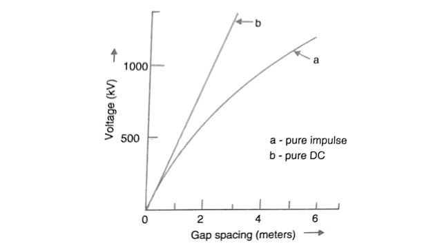
The geometry between the conductor and the tower can be viewed as that of a rod-plane gap. The strength of such gaps is higher with the combination of impulse and direct voltage than with pure impulse alone. This behavior is shown in Fig. where the CWS is plotted as a function of the gap length.
The flashovers are caused by lightning strokes which usually affect one pole of the bipolar line. Due to the coupling between the two poles, overvoltages can occur in the healthy pole. The insulation design must take this into account and prevent consequential faults on the healthy pole.
Transient Overvoltages in DC Line
Pole-to-ground faults in bipolar DC lines can result in transient overvoltages in the healthy pole of magnitudes exceeding 2.0 p.u. (although typically they are 1.7 p.u.). The maximum overvoltage occurs at the midpoint in a pole when the fault is also at the midpoint of the other pole. For off-center faults, the maximum overvoltage occurs at a location that is a mirror image of the fault location (concerning the midpoint). For example, if a fault occurs at a point of one-third distance from the sending end, the overvoltage occurs at a point of one-third distance from the receiving end.
There are two modes of traveling waves on a bipolar DC line. One is termed the pole-to-pole mode (analogous to positive sequence) while the other is termed the pole-to-ground mode (analogous to zero sequence). If the pre-fault voltage is V at a given location, it can be shown that immediately after the fault, the voltage at the other pole rises by an amount Δ V, given by
Δ V = [(Z0 – Z1) / (Z0 + Z1)] V
Where Z1 and Z0 are the surge impedances of the first and the second modes respectively. Generally Z0 > Z1 For typical values of Z0 and Z1, Δ V = 0.3V.
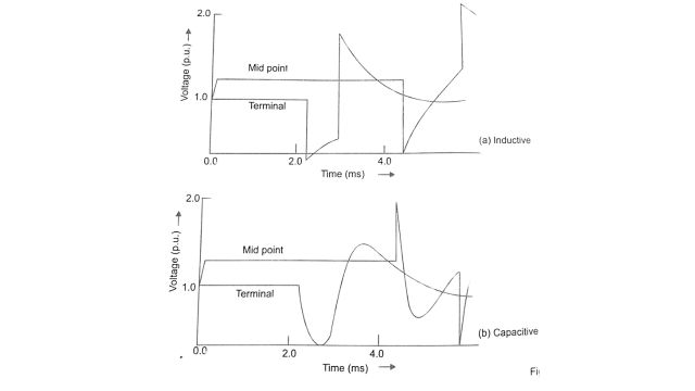
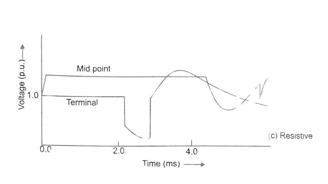
The traveling waves originating at the fault location travel in both directions and are reflected by the terminals. The kind of termination at the converter station-inductive, capacitive, or resistive has a bearing on the voltage waveform at the converter and in the line. The typical voltage waveforms at the midpoint and the terminal are shown in Fig for (i) inductive, (ii) capacitive, and (iii) resistive terminations. The parameter of the DC filter also affects the nature of the terminal voltage waveform. The following conclusions can be drawn from a digital computer study of the transient overvoltages.
- With capacitive termination to the wavefront, overvoltage in the unfaulted pole is caused by pole-to-pole mode. The attenuation and distortion of this mode is slight.
- The surge capacitor, while helping to reduce the overvoltage at the terminal, does this at the expense of the DC line. It is desirable to use a surge arrester to protect the terminal against overvoltages.
- The resistive termination to the wavefront with R = Z1, is the best and can be achieved by putting R = Z1 in the high pass DC filter and not having a surge capacitor.
- With inductive termination to the wavefront, overvoltages are caused by the pole-to-ground mode for which the attenuation is substantial. But the overvoltage at the terminal is high.
- It is desirable to provide extra insulation around the middle portion of the DC line to take care of the highest overvoltages that may occur in that zone.
- With capacitive termination, the lowest limit on the dv / dt setting of the line fault protection is determined by the maximum fault resistance above which the fault will not be detected.
It is also necessary to provide a time delay in the operation of the protection (using dv/dt) to prevent the tripping of the healthy pole. Typically, a time delay of about 3 milliseconds may be adequate. The tests carried out on the Pacific intertie and subsequent simulation using a digital computer have shown that the modeling of frequency-dependent characteristics of the line for both modes is essential for accurate prediction of the overvoltages.
Protection of DC Line
The fault current immediately following a fault is limited by the surge impedance and is of the order of 2.0 p.u. The current controller at the rectifier acts to limit this current to the prefault current. If the inverter current control is also active and power reversal in the inverter is permitted, the inverter current is maintained at a value that differs from the rectifier current by the current margin. This implies that the fault current in a steady state is equal to the current margin (of the order of 0.1 p.u.). Although this is much less than the currents in AC line faults, the clearing of the fault requires the current to be brought to zero, and sufficient time is given for the deionization of the arc path.
For fast clearing of DC line faults, the inverter mustn’t be allowed to operate as a rectifier, and the rectifier is put into the inverter mode by a sudden increase in the delay angle to its maximum limit (about 135°). The converters at both terminals then help in discharging the energy stored in the DC circuit (in capacitances and inductances) and delivering it to the AC system. The current and voltage in the DC line fall to zero and help in deionizing the arc path. After some time has elapsed (say 0.2 to 0.5 sec), the line may be automatically energized by restarting the converters (in the usual manner by ramping up the direct voltage and current). If the restart is unsuccessful, due to a persistent fault, the protective action will deenergize the line again. Normally three attempts are made to restart automatically with increasing dead time. The failure to restart even after 3 attempts implies a permanent fault and requires the shutdown of the link until the fault is located and cleared. Alternately, reduced voltage restart may be tried out if the insulation failure is due to heavy pollution on the line insulators and in bad weather.
The automatic de-energization and restarting of the DC link is similar to the clearing of the fault and automatic reclosure in AC lines. The major difference in the two cases is that while breakers are used in AC lines, the clearing and restarting are performed in DC systems using only converter control with the help of protective relays.
1. Detection of Line Faults
As mentioned earlier, the normal converter control is not adequate for clearing the fault. The de-energization of the line by driving the rectifier into the inverter mode requires special control action which is initiated on detecting the line fault.
The detection of the line fault is based on one of the following conditions: (i) a sudden drop in the DC voltage measured on the line side of the reactor, or (ii) sustained low direct voltage.
Mathematically the two conditions can be expressed as
(i) Vd < k1 and dVd / dt < – A for a duration of 𝜏 > 𝜏1
(ii) Vd < k2 for a duration of 𝜏 > 𝜏2
where k1, k2, and A are positive parameters that are chosen along with 𝜏1 and 𝜏2
The criteria for selecting these parameters are as follows:
- Selectivity: To ensure that the protection operates rapidly for DC line faults and not for AC faults or converter faults. The smoothing reactor prevents the rate of voltage drop in the line from exceeding a limit for AC and converter faults. By choosing A higher than this limit, it is ensured that the voltage derivative unit does not operate for faults other than DC line faults. Selectivity is desirable as the dead time required for deionization of the arc path in the case of DC line faults is unnecessary in the case of AC or converter faults. To ensure that the DC fault protection does not operate for AC faults, it is also necessary to set ka below a certain limit determined by the most common AC faults (single line to ground faults). Furthermore, by setting it to greater than the clearing time of AC breakers, the operation with multiphase faults is also avoided. Alternatively, low AC voltages can be used to block the operation of the voltage level unit (which operates subject to the second condition).
- Sensitivity: The DC line protection must operate satisfactorily for normal values of the arc resistance. This puts an upper limit on A.
- Reliability: The protection must operate reliably for all DC line faults including faults through a high resistance. This is the reason for providing the voltage level unit. k₁ and t, are selected such that the protection does not operate for the healthy pole (and only for the faulted pole). This is essential as, in bipolar DC lines, the power can be transmitted at sufficient levels even after a monopolar ground fault.
2. Protection Against DC Line Faults with VSC
Unlike in CSC-based HVDC links, the DC voltage in VSC-based links cannot be reversed and the DC capacitors at both rectifier and inverter stations discharge into the faults. In addition, the VSC can feed current to the fault. The blocking of the converter does not help as the free-wheeling diodes will continue to feed the fault. This implies that in detecting DC line faults, the converters need to be isolated from the AC system by opening the AC breakers. As an alternative, a DC breaker can be employed to isolate the converters from the DC line, when a line fault is detected. This can be faster than the operation of the AC breakers.
The VSC-based HVDC projects commissioned, so far, invariably use DC cables instead of overhead lines. Although the cable faults tend to be permanent, the probability of cable faults is much less than in an overhead line in which temporary insulation failure can occur due to lightning strikes or due to tree branches, pollution, or mechanical failures.
Effects of Proximity of AC and DC Transmission Lines
For reasons of economy and constraints on the right of way, AC and DC lines may be situated in the same right of way. Also, it is possible to have them on the same tower when one circuit of an AC line is converted to a DC line. Some studies have been reported on the effects of the proximity of AC and DC lines.
Nakra et al. reported from a simulator study that contact faults between a DC pole and an AC phase result in the superposition of AC voltage and currents on the DC line and DC voltages and currents on the AC line. This can result in transformer saturation in some phases and overvoltages in other phases (up to 2.0 p.u.). Otherwise, they did not find the appreciable effect of electromagnetic coupling between AC and DC lines under steady-state.
In contrast, Larsen et al. report the possibility of steady-state induction of fundamental frequency voltages in DC lines due to proximity, which can cause saturation of converter transformers. To avoid problems associated with transformer saturation, they recommend that the fundamental frequency current in the DC line be restricted to 0.1% of the rated DC. To limit the induction of AC voltages in DC lines, they suggest the use of DC filters, control modulation, and transposition of AC and DC lines. Chopra et al. have observed the possibility of large zero sequence transients in AC lines caused by transients in neighboring ground return DC lines. A study was carried out to explain the tripping of AC lines in a common corridor due to the operation of ground current relays. This event happened at the Nelson River HVDC link when the transition of metallic return to ground return took place. Interestingly, the AC line was at a distance of over 180 meters from the DC lines. From an analytic study, the authors observe that the phenomenon is due to magnetic coupling between two circuits and is affected by ground resistivity. The zero sequence currents induced on AC lines are of low frequencies (1-30 Hz) and occur during transients. No induction is present in a steady state.
The effect of interactions of electric field and ion flow in hybrid AC/DC lines has been reported. According to a study by Maruvada and Drogi, the presence of alternating field components has a negligible effect on the trajectories of ions emitted by DC conductors. For lines on the same tower, ionized fields resulting from DC conductors in corona can cause direct current induction in AC lines. The maximum current induced can be around 0.4 mA per km length of the line. With an AC circuit below the DC circuit, there is a significant screening effect on the electric field, current, and charge distribution at the ground level. However, the maximum field at the conductor surface is increased substantially resulting in higher RI and AN.
Clairmont et al. show that DC conductors in adjacent towers can shield the AC electric field and vice-versa. They use the concept of sensation level to characterize field interactions and state that below a critical separation level, the effects of proximity of AC and DC lines should be considered. The critical separation for a 400 kV DC line and a 230 kV AC line, is less than 40 ft. while for a 800 kV line, it is 110 ft.
Frequently Asked Questions (FAQs)
-
What is the function of a smoothing reactor?
A smoothing reactor, used in electrical systems, helps reduce ripple voltage and current in DC circuits by smoothing out fluctuations. It accomplishes this by impeding sudden changes in current flow, enhancing stability, and improving the performance of connected devices.
-
What is the meaning of DC line?
A DC line refers to a transmission line used to carry direct current (DC) electrical power from one location to another, typically over long distances, with minimal power loss and voltage drop.
-
What is the protection of DC line?
The protection of a DC line involves various measures to safeguard it from faults and abnormalities. This includes overcurrent protection, differential protection, ground fault protection, and surge protection devices to ensure safe and reliable operation of the DC line.
Read Also:
- DC Breakers | Characteristics, Types, and Applications
- Static Relay | Components, Working, Types, and Applications
- Comparators | Definition, Types of Comparators
- Instrument Transformer | Introduction, Types, and Need
- Static Relays I Basis, Classification, and Components


Leave a Reply