Table of Contents
Introduction
The converters in conventional HVDC power stations are line-commutated, which implies that the current initiation in the valve can only be delayed concerning the zero crossing of the converter bus AC voltage. This results in lagging power factor operation of the converters, requiring reactive power sources connected at the converter bus for better voltage control. The reactive sources are required at both the rectifier and inverter stations. While the rectifier station appears as a load in the system, the inverter station can be viewed as a generator consuming reactive power. This characteristic of the inverter is generally not desirable and requires suitable modifications by providing adequate var compensation.
The reactive power sources that are used vary from switched capacitors to static var systems. The requirements of voltage control and the costs dictate the choice of the speed of response of the reactive power control under dynamic conditions. The operations of weak AC systems can be problematic due to voltage instability and dynamic overvoltages. A better coordination of various sources is desired under such conditions. The ease of control of firing angles makes it possible to operate the converter as a static var compensator in addition to power conversion. This feature of the converter control is being increasingly used in modern HVDC converter stations.
In this chapter, the characteristics of reactive power sources employed in a converter station are described. The reactive power requirements of the converter and how they are affected by the converter control methods are presented. The var control during transients is discussed along with the description of the static var system.
Reactive Power Requirements in Steady State
1. Conventional Control Strategies
DC link is operated with current control at the rectifier and the minimum extinction angle control at the inverter under normal conditions. This method of control leads to the minimum reactive power requirement at both ends.
The equations for the reactive power as a function of active power are conveniently expressed in terms of per-unit quantities. The following per-unit system is used for convenience.
Base converter voltage Vdb =(3√2 / π)Vn where Vn is the rated (line to line) voltage at the valve side winding.
Base DC cuurent (Idb )= rated DC current (Idn )
Base DC power (P db )=nb Vdb Idb
where nb is the number of bridges connected in series. Base AC voltage (on the valve side) (Vb ) =Vn
Base AC voltage ( on the valve side) (Vb) = Vn
Base AC power = Base DC power = (√18/π)Vn Idb nb
The average DC voltage across a converter bridge is given by
V¯d = V¯cos α – R¯cI¯d
where
V¯d = Vd / Vdb, I¯d / Idb, V¯ = V / Vb
R¯c = X¯c / 2
X¯ = p.u. leakage reactance of the transformer on its base.
The power factor is given by
cos ⲫ (Vd / Vdo) = (V¯d / V¯) = cos α – (R¯cI¯d / V¯)
The power and reactive power per unit is given by the following equations
P¯d = V¯ I¯d cos ⲫ
Q¯d = V¯ I¯d sin ⲫ
The equation is also valid for the inverter if α is replaced by Y.
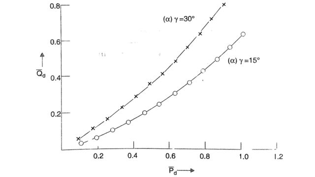
For typical values of α= 15° deg, Xc = 0.2, V = 1 the variation of Qd versus Pd (expressed in per unit) is shown in Fig.
It is to be noted that the rated DC power is less than 1 p.u. as the rated voltage is less than the DC base voltage. The two are related by
Vdn /Vdon = V¯ dn =cos ⲫn
where cos ⲫn is the rated P.F. of the converter. In the above example, the rated P.F. is 0.866. It reduces to 0.851 if the delay angle is 18°. The reactive power is around 0.6 times the real power at its rated value. The reactive power requirements can be brought down by reducing Xc For example, at Xc = 0.12 p.u., Qd is less than 0.5 Pd. The increase in the firing angle results in a sharp increase in Qd. For α = 30° Fig shows that Qd increases by about 60% at the rated power. This shows the importance of maintaining low firing angles in a steady state. However, too-low values of α can result in increased frequency of mode shifts (transfer of current control from rectifier to inverter) and too-low values of Y can result in increased incidence of the commutation failure.
The reactive power is also affected by the magnitude of the AC voltage. The reduction in V leads to an increase in Qd. However, the on-load tap changer can control V within limits. A 10% reduction of voltage from 1.0 p.u. to 0.9 p.u. requires about 15% increased current at rated power, which results in over 30% increase in the losses.
2. Alternate Control Strategies
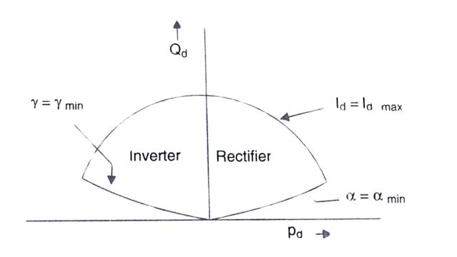
The region of operation of a converter bridge is bounded by the limits on the DC and the firing angle. Neglecting the minimum current limit, the operating region of a bridge in the Pd – Qd plane is shown in Fig which is drawn for a constant (rated) AC voltage. This region is bounded by:
- (i) Minimum a characteristic
- (ii) Minimum y characteristic
- (iii) Constant-rated DC.
In general, the locus for a constant DC is part of a circle in the Pd – Qd diagram, and the constant DC voltage characteristic is a straight line passing through the origin. These observations are made from the equations above and noting that V is a constant.
The operation at constant DC voltage implies constant power factor characteristic at the converter bus, (if the valve side AC voltage is kept constant through the action of the tap-changer). At the rectifier, the characteristic is that of a load with a lagging power factor, while at the inverter, this can be viewed as a generator with leading power factor operation. If there is no voltage support provided at the converter bus, the stability limit is considerably reduced. This is shown from the analysis of a simplified system shown in Fig. below. In Fig. (a), the rectifier is shown as a constant (lagging) power factor load while in Fig. (b) applies to the inverter operation. The phasor diagrams for both cases are shown in the Phasor diagram below.
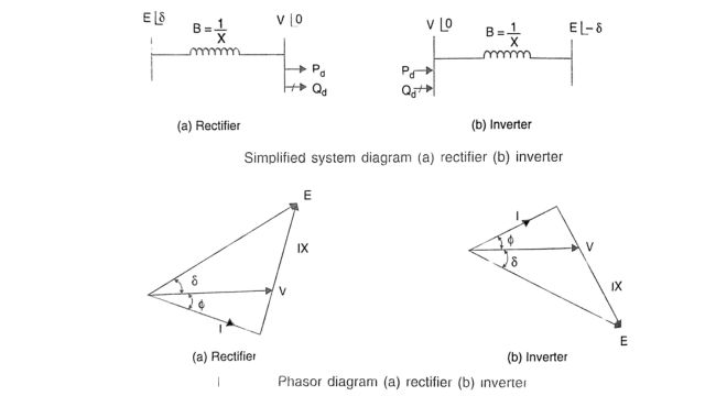
It can be shown from the phasor diagram that
V = E cos ( δ + ⲫ) / cos ⲫ
where ⲫ is the power factor angle.
The power expression is given by
P = VEB sin δ
Substituting eqns., we get
P = (E 2B cos(δ + ⲫ) sinδ) / (cos ⲫ) = (E22) / (2cos ⲫ) . [sin(2δ + ⲫ) – sin ⲫ]
It can be shown that the maximum power transfer is obtained when
δ = δm = 45° – ⲫ / 2
Pmax = E2B / 2. tan δm
The maximum power (for 30°) is given by
Pmax = 0.2887E2B
This is much less than what can be obtained in the following cases
- (i) ⲫ = 0, Pmax = 0.5E2B
- (ii) ⲫ = -30° , Pmax = 0.866E2B
- (iii) V = E, Pmax = E2B
It is to be noted that the provision of a shunt capacitor (of susceptance Bc) at the converter bus results in the modification of the maximum power expression from Eq.
Pmax = 0.2887 E2B / (1-Bc / B)
For B =3.0 p.u., Bc = 0.5 p.u. This results in an increase of 20% in the maximum power given by Eqn.
The above analysis shows that there is a need to modify the reactive power characteristics of the converter station by either:
- (i) choice of the reactive power sources or
- (ii) adjusting the converter control characteristics.
When the DC link involves long-distance transmission, the minimization of power losses in the line dictates operation at constant DC voltage and flexibility of converter operation is not feasible. However, with back-to-back links, the operation at constant voltage is not critical, and alternate converter control strategies can be adopted. These are:
- constant reactive power characteristic (ab, a’ b)
- constant leading power factor characteristic (ac, a’ c)
These characteristics are shown in Fig.
It is to be noted that by providing a constant reactive power source of qn (in per unit) at the converter bus, the characteristic ab or a’ b results in the unity power factor operation of the converter. Similarly, by providing a reactive source of 2qn and operating the converter along the characteristic ac or a’ c the power factor angle is changed from ⲫ to -ⲫ.
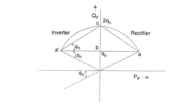
The expression for the DC and voltage for the two characteristics are given by
- (i) id = (pdn / v) [tan2 ⲫn + (Pd /Pdn)2]1/2
- (ii) id = (2qdn / v) [ 1 – (Pd /Pdn) + (Pd / (2Pdn sin ⲫn))2]1/2
Forced Commutation
The reactive power requirements of a converter can be reduced to zero or even reversed if forced commutation is used. This also helps in avoiding commutation failure in inverters.
Forced commutation involves the addition of a voltage component to the normal commutation voltage to shift the zero-crossing. One simple method of implementation is by providing a series of capacitors. This method is adopted in capacitor commutated converter (CCC).
Sources of Reactive Power
The reactive power requirements of the converter are met by one or more of the following sources:
- 1. AC system,
- 2. AC filters,
- 3. Shunt capacitors,
- 4. Synchronous condensers.
- 5. Static Var Compensator (SVC) or STATCOM.
These are shunt-connected FACTS controllers.
These are shown schematically in Fig.
From voltage regulation, losses, and stability considerations, it is not desirable to draw reactive power from the system except at low loads. The voltage regulation at the converter bus is desirable not only from the voltage control viewpoint but also from the minimization of loss and stability considerations. This requires an adjustable reactive power source that can provide variable reactive power as demanded. For slow variations in the load, switched capacitors or filters can provide some control. However, this is a discrete type of control and can result in voltage flicker unless the size of the unit, which is switched, is made sufficiently small. In contrast, the synchronous condensers, SVC, and STATCOM provide continuous control of the reactive power and can follow fast load changes.
The passive AC filters that are provided at the converter bus for filtering out AC harmonics appear as capacitors at the fundamental frequency and thus provide reactive power. These filters and shunt capacitors are mechanically switched. Although these devices are less expensive than SVC or synchronous condensers, they suffer from the inability of continuous control. Also, they can cause low-order harmonic resonances with the network impedance, resulting in harmonic overvoltages.
The synchronous condensers are essentially synchronous motors operating at no load, with excitation control to maintain the terminal voltage.
Their advantages are as follows:
- The availability of a voltage source for commutation at the inverter even if the connection to the AC system is temporarily interrupted. This also implies an increase in SCR as the fault level is increased. When the load supplied by the inverter is passive, the synchronous condenser is essential for providing voltage sources for the line commutation at the inverter.
- Better voltage regulation during a transient due to the maintenance of flux linkages in the rotor windings. The effect of the armature reaction is counteracted during a transient by induced currents in the field and amortisseur circuits.
There are also disadvantages of synchronous condensers. These are:
(i) High maintenance and cost-the former necessitated by slip rings and brushes on the rotor and (ii) The possibility of instability due to the machine going out of synchronization.
The Static Var Compensator (SVC) provides a fast response following a disturbance. The configurations normally used are:
(i) Fixed Capacitor (FC), Thyristor Controlled Reactor (TCR), or (ii) Thyristor Switched Capacitors (TSC)-TCR combination.
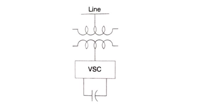
The Static Synchronous Compensator (STATCOM) based on a Voltage Source Converter (VSC) is an advanced type of SVC that is comparable to a synchronous condenser in terms of its control characteristics. STATCOM was originally named a Static Condenser (STATCON) with a very fast response, reduced maintenance requirements, and free from the problems of loss of synchronism. The VSC-based HVDC transmission does not require a separate reactive power source as the voltage source converter also functions as a STATCOM. A BTB VSC-based HVDC link can function as two STATCOMs when the DC link opens.
SVC and STATCOM
The Static Var Compensators were initially used for load compensation where the objective is to dynamically control the reactive power demand of large fluctuating loads such as rolling mills. They were subsequently used for voltage control applications in transmission systems, where, by maintaining voltage support at specified locations, it is possible to provide increased power transfer capability, control of dynamic overvoltages and improve voltage stability. By using auxiliary control signals, it is also possible to dampen low-frequency and subsynchronous frequency oscillations.
In HVDC converter stations, the provision of SVC mainly helps to have fast control of reactive power flow, thereby controlling voltage fluctuations and also to overcome the problem of voltage instability. The first example of the installation of SVC was at the Chateaguay HVDC link in Canada in 1984.
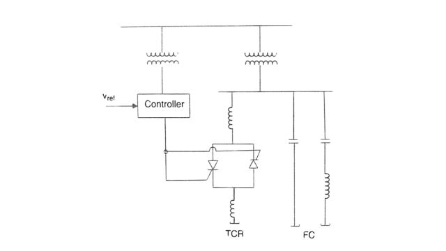
SVC is a variable impedance (or susceptance) device made up of FC (or TSC) and TCR in parallel (see Fig) while TSC (Thyristor Switched Capacitor) provides discrete control over the capacitor susceptance. TCR (Thyristor Controlled Reactor) provides continuous control of inductive susceptance, while FC or TSC does not inject harmonics, TCR injects harmonics as discussed below.
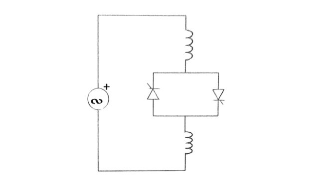
1. Thyristor Controlled Reactor (TCR)
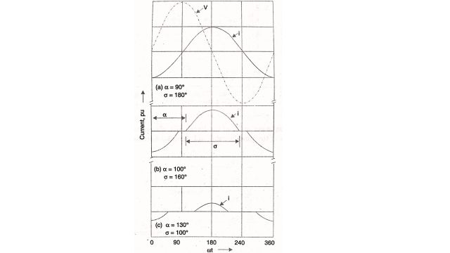
The single-phase thyristor-controlled reactor is shown in Fig. By controlling the firing angle of the back-to-back connected thyristors, the current in the reactor can be controlled.
This is shown in Fig. For a=90°, the current is maximum, while for a 180°, the current is zero.
The fundamental component of the inductor current is given by:
I1 = σ – sin σ / πXL . V
where V is the rms voltage across the TCR, XL is the fundamental frequency reactance, and is the conduction angle related to a by the following equation.
σ = 2(π – α)
The equation can be written as:
I1,= B(σ )V
where
B(σ ) = σ – sing σ. πΧL
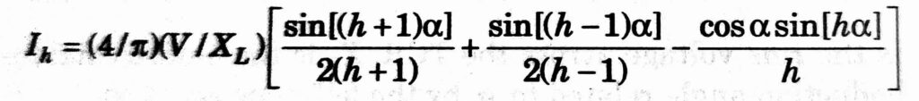
is the variable susceptance of the reactor resulting from the control action. The harmonic component of the current corresponding to the harmonic of order ‘h’ is given by
h = 3,5,7,…….
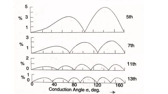
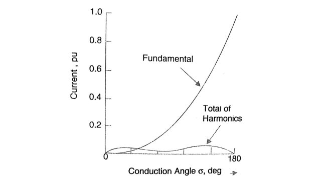
The variation of the lower order of the harmonics with conduction angle o is shown in Fig. The variation of the fundamental and the total harmonic components is shown in Fig.
The triple harmonies in the lines are eliminated by the delta connection of the three single-phase TCRs.
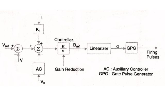
The typical control system for a TCR is shown in Fig. where the control signals are obtained from the voltage and the reactor current. The controller is usually an integral controller with variable gain to avoid the problems of control instability. The auxiliary signal V, may be derived from the bus frequency, line reactive power, or other locally measured quantities.
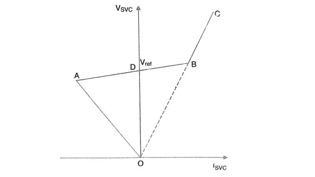
The steady-state control characteristics of an SVC in the V-I plane are shown in Fig. The control range is AB which shows a positive slope that can be adjusted from the gain in the current feedback path.
The harmonics injected by TCR into the system can be considerably reduced either with twelve pulse arrangement or with additional filters tuned to the 5th and 7th harmonies.
2. STATCOM
The schematic diagram of a static compensator, also termed a static condenser is shown in Fig. The VSC consists of either GTO thyristor switches (which are turned on and off only once in a cycle) or IGBT switches which have a much higher speed and operate up to 2 kHz.
The equivalent circuit and the phasor diagram of STATCOM are shown in Fig. Using dynamic phasors, the equation for the circuit is given by Eq. and is reproduced here.
L . dÎ / dt +(R+jωo L)Î = ṽ – Ê
where
Î = IQ + jID, ṽ = VQ + jVD = V0, Ê = kVdc∠(θ+α)
Vdc is the voltage across the DC capacitor described by the following equation
c . dVdc / dt +GVdc = mk [sin(α+θ)ID + cos(α+θ)IQ]
where G is the conductance across the capacitor (representing the losses in the capacitor). The losses in the converter are neglected. L and R are the inductance and resistance of the reactor (or the leakage impedance) between the VSC and the converter bus.
m and α are the control variables of the converter that affect the magnitude and phase angle of the voltage injected by the converter. The magnitude is normally controlled by PWM (keeping the DC voltage constant in a steady state). The control of a affects the power flow that supplies the losses in the STATCOM; whereas the control of m affects the reactive power output. In converters with GTO switches, m is normally kept constant (at the maximum possible value using square wave operation) and only a is varied to control the reactive power by varying the magnitude of the DC voltage. By increasing a, the reactive current drawn increases (note that it is assumed to be positive when it is inductive).
3. Comparison between SVC and STATCOM
While SVC is a variable impedance type compensator, STATCOM is a variable voltage type compensator. A STATCOM has several technical advantages over an SVC as given below:
- (a) Faster response (fraction of a cycle) independent of the network impedance.
- (b) Requires lesser space as bulky passive components (such as reactors) are eliminated
- (c) Inherently modular and relocatable
- (d) It can be interfaced with real power sources such as battery, fuel cell, or SMES (Superconducting Magnetic Energy Storage)
- (e) A STATCOM performs better during low voltage conditions as the reactive current can be maintained constant. It is even possible to increase the reactive current in a STATCOM under transient conditions if the devices are rated for transient overload. In an SVC, the rating of the passive components-reactors and capacitors determines the maximum reactive current. Also, the reactive current in an SVC drops linearly with the voltage drop at the limit.
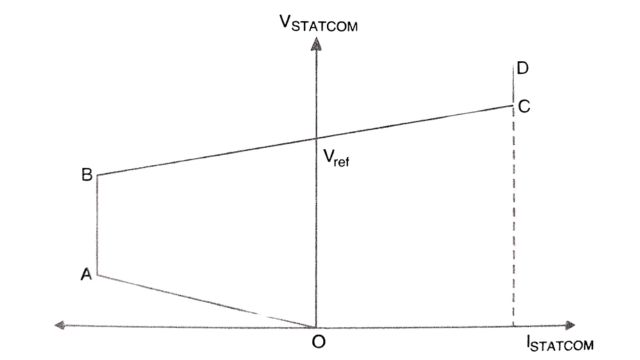
The last point can be explained with the help of steady state control characteristics of a STATCOM (shown in Fig.) and comparing it with the SVC characteristic. The reactive current limits (AB and CD) can be increased by selecting devices (GTO or IGBT) with a higher transient rating.
In reference, the dynamic performance of a STACOM at an HVDC inverter feeding a very weak AC system (SCR < 2) is investigated. It was observed from a case study, that the SVC exhibited poor dynamic performance during recovery from inverter close-in faults, caused by increased frequency of commutation failures. A simple explanation for this behavior is that the SVC causes TCR to back off during the recovery as it senses low voltage immediately after the fault is cleared. Such action reduces ESCR even further, resulting in repeated commutation failures. In contrast, the STATCOM performed satisfactorily as its equivalent circuit is similar to that of a synchronous condenser (a voltage source behind a small inductance), and the reactive current can be held constant even at lower voltages.
Reactive Power Control During Transients
The control characteristics of the reactive power sources have a bearing on the system behavior during a transient. In this context, it is to be noted that the converter control characteristics can be modified to control the reactive power demand. However, this is feasible mainly for back-to-back links.
Suitable control of reactive power is required during a transient for the following reasons:
- Control of dynamic overvoltages caused by load rejection
- Speedy recovery of power following a fault in the inverter system
- Control of instability
The dynamic overvoltages are mainly due to the excess of reactive power released by the sudden blocking of the converters. This requires a fast control of the reactive power generation from capacitive to inductive. Static Var Systems (including SVC or STATCOM) can achieve the speed, however, the initial control of overvoltage may not be feasible unless the rating of the SVS is increased, which may be uneconomic.
The distortion of the voltage waveform produced during the recovery period when the power is increased can cause commutation failures unless the rate of change of power is limited. This is crucial, particularly for low SCR. In this case, the voltage support is also critical as an increase in power can result in the reduction of voltage magnitude unless fast control of reactive power is implemented.
The voltage instability can also be a problem at low SCR and can be tackled by a suitable converter control strategy or the provision of SVS at the converter bus. The modulation of the extinction angle (Y) at the inverter has also been applied.
Frequently Asked Questions (FAQs)
-
What are the basic requirements of reactive power control?
Reactive power control requires monitoring voltage levels, adjusting reactive power output, and maintaining power factors within acceptable limits to ensure stable and efficient electrical distribution systems.
-
What are the sources of reactive power?
Sources of reactive power include synchronous generators, capacitors, and static VAR compensators, which supply or absorb reactive power to maintain voltage levels and support the operation of electrical systems.
-
What is the source and sink of reactive power?
Synchronous generators and capacitors are sources, while inductive loads such as motors are sinks of reactive power in electrical systems.
Read Also:
- Smoothing Reactor and DC Line | Transient overvoltages, Protection, and Effects
- DC Breakers | Characteristics, Types, and Applications
- Comparators | Definition, Types of Comparators
- Static Relays I Basis, Classification, and Components
- Potential Transformer | Construction, Working, and Errors


Leave a Reply