Table of Contents
Introduction
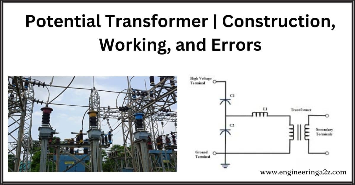
Transformers are devices that help transfer electrical power from one circuit to another. They have coils of wire that are connected magnetically. Power transformers are used in power lines to change the voltage or current levels. Instrument transformers, like potential transformers, are used to measure big currents and voltages safely. A potential transformer specifically lowers high voltages to safer levels without changing the frequency, making it easier to measure and work with electricity.
What is a Potential Transformer?
A potential transformer, or PT, is like a magic box that helps make high-voltage electricity safer to measure and protect against. It takes big voltages and turns them into smaller ones so we can use them in meters and safety devices. It works using special coils and magnets, without changing the frequency of the electricity.
Transformers, in general, are like super magnets that move electricity from one place to another. They have two coils, one for sending electricity (primary) and one for receiving it (secondary). These coils work together to transfer electricity without any physical connection. Transformers come in different types, like potential transformers and power transformers and they’re used in electrical networks to make sure everything runs smoothly and safely.
Construction of a Potential Transformer
A potential transformer is made with a special core that works efficiently at low power levels, reducing the amount of electricity needed to operate it. Its terminals are designed to keep voltage levels stable even when there’s a lot of demand and to keep the timing of the electricity consistent.
The primary part of the transformer has lots of wire coils, while the secondary part has fewer. They’re arranged in a way that reduces wasted electricity and the insulation is carefully divided to keep it safe and reliable. In simple terms, a potential transformer is built to be efficient, stable and safe for measuring electricity.
Working on a Potential Transformer
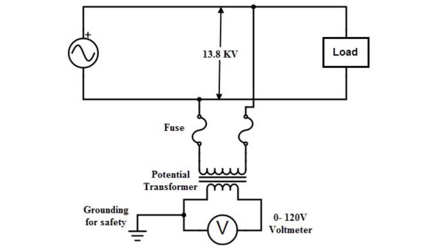
A potential transformer is like a middleman between a high-voltage power line and a voltmeter. It’s connected between the power line and the ground. The high-voltage electricity flows through its primary winding, and a lower voltage is measured across its secondary winding using a voltmeter.
Because of how it’s built, only a tiny bit of electricity flows through the secondary winding, making it safe to measure. Think of it like a water pipe: the potential transformer reduces the high-pressure water to a lower pressure that’s safe for us to use.
These transformers are designed to handle a specific range of power, usually between 50 and 200 volts (VA). They work quietly in the background, ensuring we can safely measure high-voltage electricity without any risk.
According to the convention transformer, the transformation ratio is:
V2 = N1 / N2
‘V1’= voltage of the primary winding
‘V2’ = voltage of the secondary winding
‘N1’= number of turns in the primary winding
‘N2’= number of turns in the secondary winding
The high voltage of a circuit can be determined by using the above equation.
Potential Transformers Classification
Potential transformers can be classified into the following forms based on their function.
- Metering voltage transformers
- Protection voltage transformers
- Electromagnetic Potential Transformers
- Capacitive Potential Transformers
1. Metering Voltage Transformers
A metering potential transformer is like a translator between high-voltage power lines and voltmeters. It steps down the voltage so it’s safe to measure, allowing accurate readings. It’s like a small, silent helper ensuring safe electricity measurement.
2. Protection Voltage Transformers
Single or three-phase metering potential transformers are super accurate. They’re used to power and monitor measuring tools, relays, and other gadgets. They ensure everything works smoothly and accurately, making electricity measurements safe and reliable.
3. Electromagnetic Potential Transformers
These transformers are similar to regular transformers, with coils wound around a center. They handle voltages above or below 130KV. One part is connected to the power line, and the other to the ground. They’re used in relays, meters, and high-voltage systems.
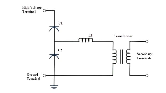
4. Capacitive Potential Transformers
These transformers, also known as capacitive potential transformers or dividers, come in two types: bushing and coupling. They use a series of capacitors on either the primary or secondary side to measure voltage. They’re used for power cable communication but are more expensive.
Errors in Potential Transformers
In primary instruments, the output on the secondary side matches the secondary transformer’s value. However, in potential transformers, voltage drops and power factors cause errors like phase shifts and voltage inaccuracies.
1. Ratio and Phase Angle Errors of Potential Transformer
In an ideal potential transformer, the primary and secondary values are accurately related, with the secondary voltage being exactly opposite in phase to the primary voltage. However, in reality, due to voltage reductions in both primary and secondary sides, we need to consider both values in the system.
2. Voltage Ratio Error
The voltage ratio error compares the sensed voltage with the expected voltage. It’s calculated using a formula that considers the difference between the actual and expected values.
RatioError = Kt Is – IP / Ip
The percentage voltage error measures this difference in terms of a percentage of the expected voltage.
VoltageError = (Vp – Kt Vs / VP) . 100
3. Phase Angle Error
The phase angle error occurs when the voltage in the secondary section, which should be exactly opposite in phase to the primary voltage, isn’t aligned correctly. Adding more devices to the relay connected to the secondary side can increase these errors in potential transformers.
Advantages of Potential Transformer
- Provide accurate and reliable measurements of high voltages.
- Essential for safe and efficient operation of power systems.
- Isolate high-voltage systems from lower-voltage control and measurement systems, ensuring safety.
- Typically less expensive than other high voltage measurement devices.
- Highly reliable with minimal maintenance, reducing downtime and increasing efficiency.
Disadvantages of Potential Transformer
- Operate within a specific frequency range; accuracy may be affected outside this range.
- Designed for measuring high voltages within a specific range, not suitable for extremely high-voltage applications.
- Sensitive to external factors like temperature, humidity, and electromagnetic interference, affecting accuracy.
- Requires complex wiring for proper connection to other power system components, time-consuming.
- Not accurate for low voltage measurements, limiting use in some applications.
Applications of Potential Transformer
- Mainly for measuring high voltages.
- Electrical protection.
- Metering devices for energy billing.
- Monitoring industrial load.
- Power line carrier communication networks.
- Synchronizing generators and feeders.
Frequently Asked Questions (FAQs)
-
What do you mean by potential transformer?
A potential transformer is an instrument transformer used to step down high voltages to safer levels for measurement and protection purposes in electrical systems.
-
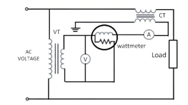
What is the use of CT and PT?
CT (Current Transformer) and PT (Potential Transformer) are special transformers used in AC power systems. They measure large currents and voltages, reducing them to safer levels for monitoring and protection.
-
What is the working principle of a transformer?
Transformers operate based on Faraday’s law of mutual induction. This law says that when the magnetic field around a circuit changes, it creates an electric current in the circuit.
-
What is the efficiency of a transformer?
Transformer efficiency is the percentage of output power compared to input power. It shows how well a transformer converts electrical energy. Efficiency is typically between 97% and 99%.
Related Posts
- Difference Between HVDC and HVAC

- Different Types of Faults in Overhead Transmission Lines

- Circuit Breaker | Types of Circuit Breaker

- Tariff: Definition, Types, Objectives & Characteristics of Tariff

- AC and DC System : What is AC and DC Transmission System

- Buchholz Relay | Construction and Working Principle


Leave a Reply