Table of Contents
Introduction
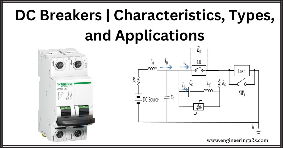
The development of HVDC circuit breakers has been underway for some time in the late eighties, and a 500 kV breaker with current interrupting capability up to 4000A, has been reported. Although several types of DC breakers have been developed by different manufacturers, the basic concepts are the same in all cases.
Basic Concepts of DC Circuit Interruption
The major problem in the current interruption in DC circuits is that there is no natural current zero as in the case of AC circuits. The current can be brought to zero only by applying a counter voltage higher than the system voltage. The second problem is the dissipation of large energy stored in the inductance of the circuit.
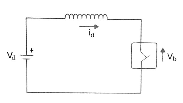
Consider the simple representation of the DC circuit shown in Fig. The breaker has a counter voltage Vb. It can be shown that the energy absorbed by the breaker is
Wb = 1/2 LI2d (Vb / (Vb – Vd))
and the time required to bring the current to zero is given by
Td = LId / (Vb – Vd)
where Id is the current in the breaker before the interruption. The reduction has a significant effect on the breaker costs as Wb is decreased which results in the reduced requirements of the energy capability of a breaker.
The current Id is brought down to the rated value by the normal action of the current control in converters. Although this requires a certain amount of time (say 30 to 50 msec), the time required for interruption reduces. The alternate strategy is to interrupt the fault current fast but this will increase the interruption time Ti apart from increasing the cost of the breaker.
The counter voltage produced by the arc that is struck when the breaker contacts separate is not sufficient in HVDC breakers. This requires an auxiliary circuit in which a capacitor is inserted to develop the required counter voltage. However, a capacitor is unable to dissipate the energy and the current in the capacitor has to be commutated to nonlinear resistors which then dissipate the energy without undue increase in the voltage across them.
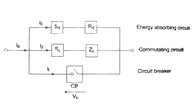
The general arrangement of an HVDC circuit breaker is shown in Fig. The current in the breaker (when closed) is normally carried through CB with moving metallic contacts. This may be a vacuum, oil, airblast, or SF6 device. After a trip signal is given to the breaker, the breaker contacts open to draw an arc. This is initiated at time ti (see below Fig. which shows the current and voltage waveforms).
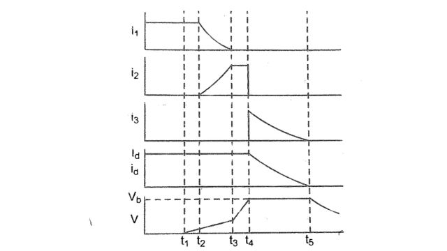
A short time later at t2 the commutation circuit is inserted through the insertion device Sc. The commutating impedance is primarily made up of a series L-C circuit which is tuned to a certain frequency. The capacitor may or may not be charged. The insertion device Sc may be a triggered vacuum gap or spark gap or in the so-called ‘passive commutation circuit, just a solid connection (no switching required). The main purpose of inserting a commutating impedance is to create a current zero in CB and transfer the current to Zc with sufficient contact separation in CB to regain its dielectric strength. This current transfer is completed by time t3 The DC circuit current id flowing through the capacitor in Zc rapidly builds up to a high voltage Vh across the breaker. When the voltage reaches Vb at time t4 the energy absorber Rd is inserted through the device Sd The nonlinearity of the resistance Rd as a switch closes when its clipping voltage is reached. The direct current now decays to zero by discharging its energy to Rd after the interval of Ti ( time t5 range. The breaker operation is completed by t5 if the three parallel paths CB, Ze, and Rd have adequate voltage withstand capability. Otherwise, fast-acting isolators that operate at zero current level may be used to prevent overstressing of the breaker until the converter control restores the voltage to a level that can be withstood by the breaker under steady-state conditions.
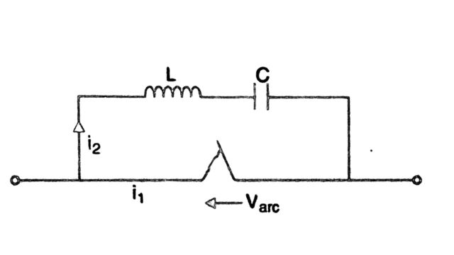
In the passive commutation method, a series L-C circuit is connected across СВ. The interrupter element CB is an air blast or SF6 breaker similar to that used in AC circuits. Field tests have shown that the air blast breaker is superior in performance compared to SF6.
The commutation of the current to Zc in the passive commutation method is initiated by the arc itself. The differential equation for the current (see Fig.) is given by
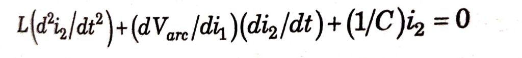
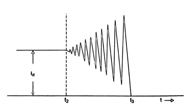
Since the voltage decreases with the current, its differential resistance d Varc / di1, is negative. This causes the build-up of increasing current oscillations in the circuit and the current goes to zero when the amplitude of the oscillations reaches the value of direct current id (see Fig.). While this is a simple explanation of the phenomenon, the process of commutation is affected by the geometry of the breaker nozzle and the interruption chamber, the natural frequency, and the stray resistance of the circuit. The increase in the oscillation magnitude may also occur in steps.
Characteristics and Types of DC Breakers
The breaker is characterized by four variables of interest in its application to the system. These are:
- Voltage capability
- Current capability
- Energy capability
- Switching time
The voltage capability is related to two parameters:
- (i) The voltage during the interruption process and
- (ii) Steady-state operating voltage and transients in the system.
The breaker voltage requirements can be kept low by coordination with converter control and fast isolators. But this is not desirable. In general, the highest permissible voltage gives the best performance in terms of lower energy absorption and shorter switching time.
The interrupting capability of a breaker does not have to be much above the rated current in the circuit, because the converter control can be relied on to bring the fault current down to the rated levels. The required energy capability of a breaker depends upon many factors such as the inductance, converter voltage, and current, breaker voltage, and the duty cycle. In HVDC breakers, series-connected modules are used to give the required voltage and energy capabilities.
The switching time of a breaker includes the following components:
- (i) Time required to generate the trip signal
- (ii) Time required to separate the contacts in the main breaker
- (iii) Time required to commutate the current to Z,
- (iv) Time required to commutate current from Z to R (energy absorbing circuit)
- (v) The interruption time (T)
- (vi) Time required to bring the DC system back to steady-state post-fault condition.
While the first component can be kept small (say 2 ms for station faults), there is no real advantage in generating the trip signal much faster than the time taken to reduce the fault current using converter control (around 30-50 ms).
The second component is around 10 ms. The third and fourth components can be reduced by using a charged capacitor in the commutation circuit. Again, there is no real advantage in keeping the total time below 10 ms as there is the problem of restriking the area in the main breaker
The interruption time is related to Vb and Id. The voltage is normally around 1.7 p.u. The reduction in Id reduces Ti, linearly. The last component depends on the voltage capability of the breaker. With low voltage capability, this component of the switching time could be of the order of 100 ms due to the time required for the operation of the isolator, the converter control, and the communication delay (required for coordination of the breaker operation and converter controls).
The above analysis shows that there is a significant saving in switching time possible by increased voltage capability while the current capability may be limited to the rated current. The requirements on the switching time depend on the AC system requirements for maintaining DC power flow in transient conditions, taking into account the considerations of system stability.
Applications of DC Breakers
The application of DC breakers is required mainly for fault clearing in MTDC systems. However, even for two terminal DC systems, the DC breakers can be useful in the following situations:
- When the converters feed two parallel DC lines
- When parallel connected converters feed the same line
- When current needs to be transferred from the ground return to the metallic return during the monopolar operation. The breakers for this application are termed as Metallic Return Transfer Breakers (MRTB). Although the voltage capability required for this application is moderate, the energy capability required may be substantial.
Frequently Asked Questions (FAQs)
-
What is the DC breaker?
DC circuit breakers halt excessive current flow, shielding components from harm and preventing hazards. They interrupt current surpassing set limits, ensuring safety and safeguarding electrical systems in DC power distribution setups.
-
What is the difference between a DC and an AC breaker?
DC breakers interrupt direct current flow, while AC breakers interrupt alternating current. DC breakers require different design considerations due to continuous current flow.
-
Why DC supply is used in circuit breakers?
DC supply is used in circuit breakers for reliable operation. It ensures uninterrupted functionality even during power fluctuations or failures. DC power provides consistent energy to control circuits, enabling swift and precise response to electrical faults.
-
Are DC breakers directional?
Yes, DC breakers are directional because they are designed to interrupt the flow of direct current in a circuit in one direction only.
-
How to wire a DC circuit breaker?
1. Choose a safe location for the DC circuit breaker.
2. Turn off the power to the circuit.
3. Pick the correct wire size.
4. Connect the terminals of the circuit breaker securely.
Read Also:
- Instrument Transformer | Introduction, Types, and Need
- Potential Transformer | Construction, Working, and Errors
- Electrical Cable | Components, Types and Application
- Distribution Systems | Classification and Challenges
- Transmission Line | Introduction, Classification, and Modelling


Comments (4)
can DC breakers be mounted horizontally or will that affect its arc suppression?
Most DC breakers can be mounted horizontally, but it’s best to check the manufacturer’s guidelines. Some breakers rely on gravity for arc suppression, so mounting them in the wrong position could affect performance.
Hey, I think your site might be having browser compatibility issues.
When I look at your blog in Chrome, it looks fine but when opening in Internet Explorer, it
has some overlapping. I just wanted to give you a quick heads up!
Other then that, great blog!
Thank you for your comment! We appreciate your feedback and will work on resolving the issue.