Table of Contents
Introduction
A relay detects the change between normal and abnormal conditions by comparing two electrical vector quantities, both of which are derived from the system voltages and currents at a particular relay location. A variety of characteristics can be obtained on the complex plane with the help of multi-input devices. A comparator is also a basic form of a multi-input device, although more than two inputs increase the range of complex characteristics so that special characteristics of the form: ellipse, parabola, quadrilateral, parallelogram, etc., can be obtained. Most of the protective schemes employ two-input devices only. The function is generally defined by the relationship between the inputs, which govern the boundary conditions of operation.
Depending on the specific method of comparison all comparators can be grouped as either:
- (a) Amplitude comparator or
- (b) Phase comparator
The analysis of amplitude and phase comparators shows that there is no difference between the two. The semiconductor comparator affords great freedom of design for specific laws of operation and/or characteristics, this has no counterpart in the electromechanical relay, where the basic characteristics are prescribed by the behavior of the element itself.
Amplitude Comparator
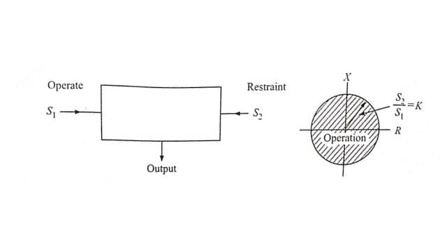
If the two input signals are S1 and S2 the amplitude comparator gives positive (yes) output only if S2 /S1 ≤ K [Fig.], S1 is the operating quantity and S2 is the restraining quantity. Ideally, the comparison of the two input signals is independent of their level and their phase relationship. The function is represented by a circle in the complex plane, with its center at the origin: this defines the boundary of the marginal operation.
Statie-amplitude comparators may be of the following types:
(i) Integrating comparators,
(ii) Instantaneous comparators, and
(iii) Sampling comparators.
1. Integrating Comparators
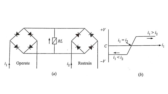
It is possible to arrange rectifier bridge networks as amplitude comparators. Rectifier bridge comparator can either be of circulating current type or opposed voltage type. The basic circuit for the circulating current type is shown in Fig.(a) The polarized relay operates when S1 > S2, where S1 = K1 i2 and S2 = K2 i2. This arrangement provides a sensitive relay whose voltage may be ideally represented by Fig.(b). The relay voltage will never exceed twice the forward voltage drop of one of the rectifiers and typically will be of the order of 1 volt.
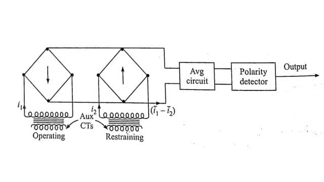
Instead of the polarized relay, a static integrator can be used consisting of an averaging circuit and the polarity detector circuit as shown in Fig. The two currents i1 and i2 are rectified, and their difference (‾i1 – ‾i2) is averaged. The output is obtained only if the averaged value is positive.
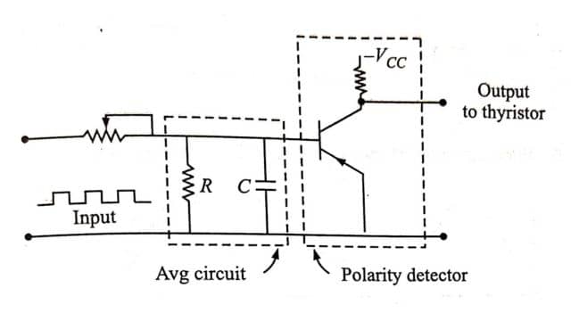
An integrator circuit is shown in Fig. The tripping occurs when the capacitor voltage reaches the setting value of the level detector and triggers a thyristor.
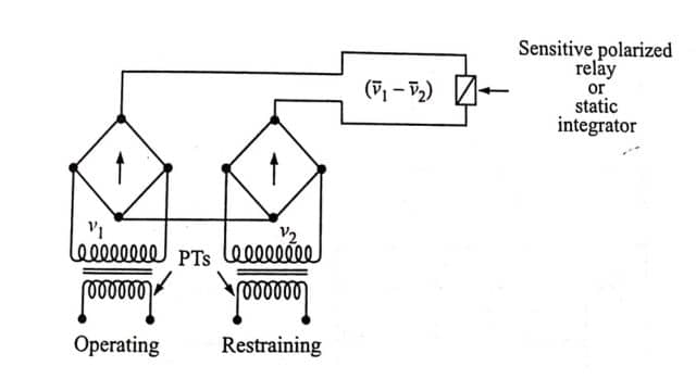
The opposed voltage type comparator shown in Fig. works with voltage input signals derived from PTs. The operation in this case depends on the average difference of the rectified voltages (‾v1 – ‾v2). In this case, the limiting action is the wrong way, as the rectifiers have higher resistance at lower voltages. Also, the rectifiers are not protected at higher currents.
2. Instantaneous Comparators
Instantaneous or direct amplitude comparators can be of two types: averaging type and phase splitting type.
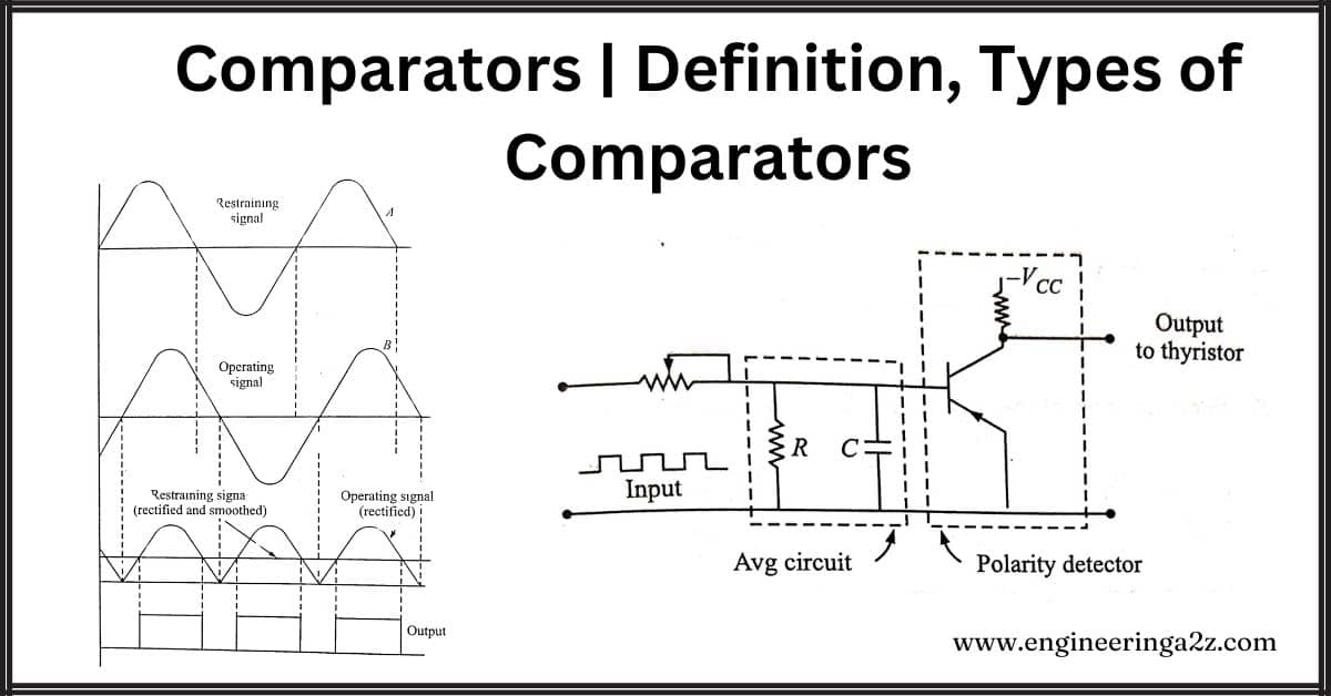
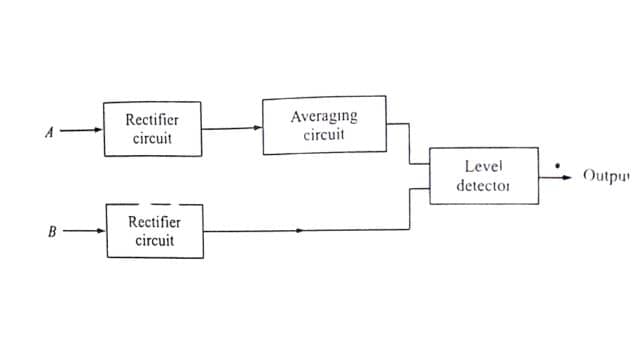
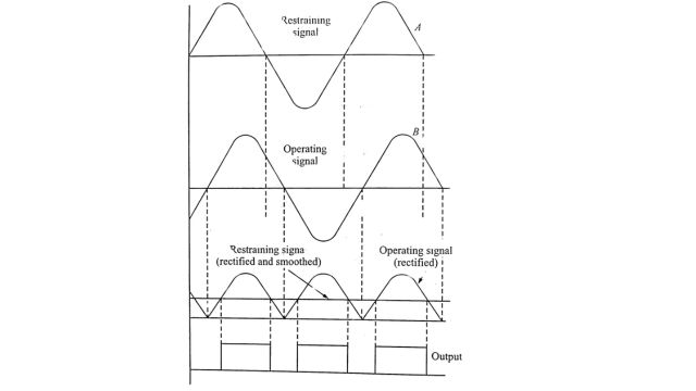
In the averaging type instantaneous amplitude comparator, the restraining signal is rectified and smoothed completely to provide a level of restraint. This is then compared with the peak value of the operating signal, which may or may not be rectified, but is not smoothed. The tripping signal is provided if the operating signal exceeds the level of restraint. The block schematic diagram is shown in Fig. (a). The wave shapes are shown in Fig. (b).
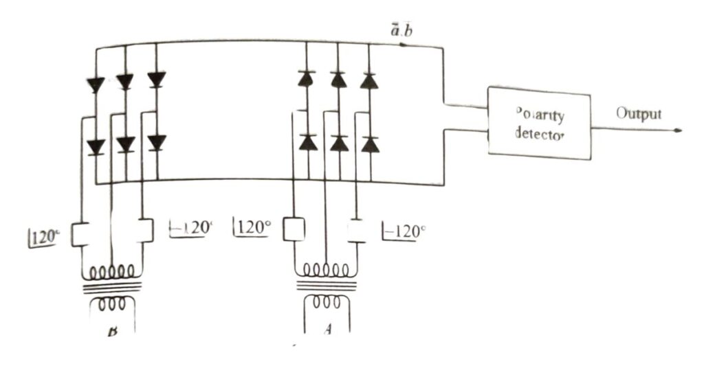
Since the above method involves smoothing the operation is slow. A faster method is phase splitting before rectification as shown in Fig. Here the input is split into six components 60° apart so that it is smoothed within 5%. The averaging circuit can be eliminated. The operating time here is determined by the time constant of the slowest arm of the phase-splitting circuit and by the speed of the output device.
3. Sampling Comparators
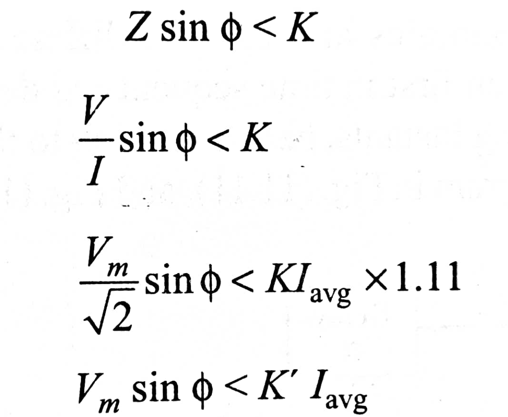
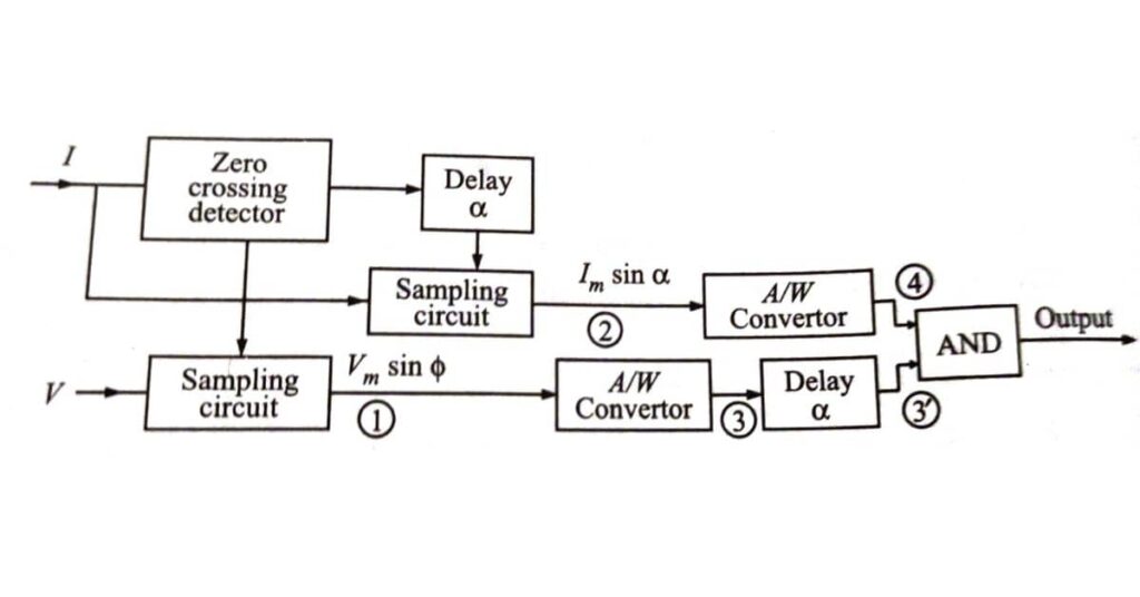
Sometimes it is convenient to get the required characteristics by comparing the magnitude of one input signal at a certain point on its wave against the rectified and smoothed value of the second signal. The reactance characteristic is one such case where the instantaneous value of the voltage at the moment of current zero is compared against the rectified and smoothed value of the current. If current I lags behind voltage by V by an angle & then the value of the voltage at current zero is Vm sin o The reactance relay operates for X < K, i.e.,
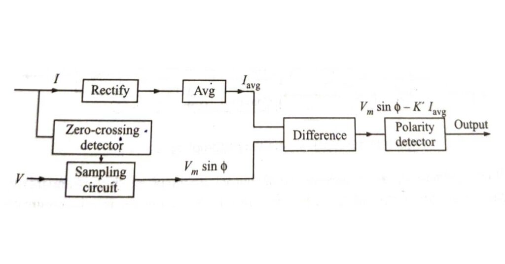
The block schematic diagram is shown in Fig. given below.
It is also possible to compare the instantaneous magnitude of one signal at a certain moment with the instantaneous magnitude of the second signal at that very moment or a certain other moment. It simply means that one or both signals can be sampled.
For the same reactance relay of the previous case, for operation, we have,
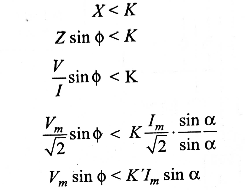
A comparison of two instantaneous magnitudes here is made by converting the magnitudes into proportional pulse widths and then comparing them with the help of an AND gate. If the two samples are taken at different instants, the pulse width representing the one taken first in the time sequence is delayed by the time difference between the two sampling instants, before feeding to the AND gate.
By using sampling techniques we can dispense with the phase shifting and mixing circuits. The elimination of phase shifting and mixing facilities requires a greater degree of sophistication in the relay circuitry but achieves a saving in both space and cost. The measuring circuits are isolated from the transformer secondaries, except during the 50 µs sampling period in each half cycle, and the possibility of maloperation due to spikes on the input waveforms is remote.
Phase Comparator
The phase comparison technique is the most widely used for all practical directional, distance, differential, and carrier relays. If the two input signals are S1 and S2 the output occurs when the inputs have a phase relationship lying within specified limits. Both inputs must exist for an output to occur, ideally, operation is independent of their magnitudes and is dependent only on their phase relationship. The figure illustrates the phase comparator in its simple form. The function as defined by the boundary of marginal operation is represented by two straight lines from the origin of the complex plane.
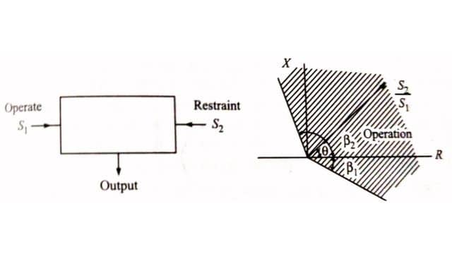
where θ is the angle by which S2 leads S1. If β1 = β2 = 90° the comparator is known as a cosine comparator and if β1 = 0 and beta β2 = 180° it is a sine comparator.
Static phase comparators may be of the following types:
(a) Vector product comparator.
(b) Coincidence type phase comparator.
Amongst the vector product comparators are the Hall effect phase comparator and the magneto-resistivity phase comparator.
Coincidence Type Phase Comparator
The basic concept of phase comparison is simpler in that it is possible to deal with signals of equal strength whose coincidence (or noncoincidence) is readily measurable. Considering two sinusoidal signals S1 and S2 the period of coincidence of S1 and S2 will depend on the phase difference between S1 and S2 Figure illustrates the coincidence of signals for different phase relationships.
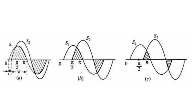
It can be seen that the period of coincidence is equal to the period of noncoincidence for a phase difference of ± 90° the period of coincidence is less than the period of noncoincidence and vice versa when the phase difference is less than ± 90°
Depending upon the phase relation of the input signals it is possible to design the circuit to give an output a Yes or a No, by measuring the period of coincidence. The period of coincidence of two signals with a phase difference of θ is Ψ = 180 – θ. Different techniques can be employed to measure the period of coincidence; the more important ones are described below.
1. Direct Phase Comparison
The number of basically different methods of obtaining useful characteristics from a direct phase comparator circuit is confined to the following:
(1) Block instantaneous comparison in which the duration of polarity coincidence determines the output. The tripping criterion is that the duration of the first coincidence should exceed a specified time, usually one-quarter of the power-frequency period
(ii) Pulse comparison in which the polarity of one signal is measured during a short interval in the cycle of the second signal, usually, but not necessarily at the latter’s peak
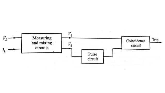
The block diagram of the pulse type of relay is shown in Fig. Line voltage and current are applied to two measuring circuits, which produce complex output voltages

Voltage V2 is applied to a pulsing circuit which produces a positive pulse once every cycle when V2 is at its positive maximum V1 and the pulse derived from V2 is then applied to the terminals of a coincidence circuit of the type requiring both input terminals to become positive before producing any potential change at its output terminals. The criterion for relay operation is thus defined, since the coincidence circuit only yields an output when the pulse is present, and then only if V1 is positive at this instant. If e is the angle between V1 and V2 it follows that – 90° ≤ θ ≤ + 90° for V1 to be positive at the instant of V2 maximum.
Another method for direct phase comparison is by block spike method. In this method, one input is squared and the other is turned into a spike preferably at the instant of its peak value; the spike and block signals are then fed through an AND gate. The coincidence of input signals occurs only for – 90° ≤ θ ≤ + 90°.
2. Phase Splitting Technique
In this method two phase-shifted components (± 45°) are obtained for each of the input signals and, these four components are fed to an AND gate. An output results if all four are simultaneously positive at any time in the cycle. Referring to Fig. it can be seen that output will be obtained for – 90° ≤ θ ≤ + 90°. The block schematic is also shown in Fig.
Because of the time constants of the phase-shifting circuits, the method is slightly slower than the previous method. By using two such comparators for each the time of operation can be reduced to less than half a cycle.
3. Integrating Phase Comparison
In this method, the time overlap of the two sinusoidal inputs is measured for each cycle by integrating the output of an AND gate through which they are fed. The period of coincidence is measured, and only if it exceeds 90° (for a symmetrical comparator) the output is obtained so that the condition is – 90° ≤ θ ≤ + 90°.
Frequently Asked Questions (FAQs)
-
What is a comparator in the static relay?
In relays, comparators compare phasors’ magnitude or phase. Distance relays always include phase or magnitude comparators, whether electromechanical, solid-state, or microprocessor-based.
-
What is the function of the phase comparator?
The phase comparator’s output regulates a voltage-controlled oscillator (VCO) running at frequency R Hz, which then generates the control signal for a phase-locked loop (PLL) circuit to synchronize the clock signal Sc(t).
-
What is called comparator?
A comparator in electronics compares two voltages or currents, producing a digital signal showing which is greater. It has two input terminals for analog signals and one output terminal for binary digital signals.
-
What is a voltage comparator?
A voltage comparator compares an input voltage with a set reference voltage. Its output changes depending on whether the input is above or below the reference voltage.
Read Also:
- Electrical Cable | Components, Types and Application
- Distribution Systems | Classification and Challenges
- Transmission Line | Introduction, Classification, and Modelling
- Parallel Operation Of 1 Phase/ 3 Phase Transformers
- Discharge Lamp | Classification and Characteristics


Leave a Reply