Table of Contents
Introduction
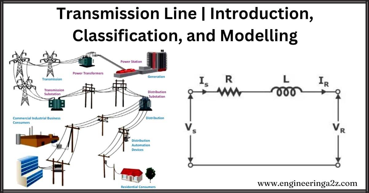
A transmission line is like a power highway for electricity to travel from a power plant to faraway places where people use it. It’s made of special wires called ACSR, which stands for aluminum conductor steel reinforced. The steel makes the wires strong. Most of the wires are aluminum because it’s a good conductor and weighs less than copper. This helps electricity travel efficiently and safely. We’ll also talk about different types of transmission lines, their characteristics, and how we model them in electrical engineering.
What is a Transmission Line?
Transmission lines are like electrical paths that help signals move from one place to another. They act as a connection between where the signal starts (transmitter) and where it ends (receiver). These lines enable electrical impulses to travel between two wires, and there’s usually something like air in between them.
Classification of Transmission Line
Transmission lines are usually sorted based on how far they go, but in real situations, we also look at frequency. So, we combine the length and frequency of a transmission line to classify them into three types.
- Short transmission line
- Medium transmission line
- Long transmission line
1. Short Transmission Line
If you multiply the length and the frequency of a transmission line and get a number less than 4000, we call it a short transmission line. For example, if the frequency is 50 Hz, the length of this line would be less than 80 km.
2. Medium Transmission Line
If you multiply the length and the frequency of a transmission line and get a number between 4000 and 10000, we call it a medium transmission line. For instance, at a frequency of 50 Hz, the length of this line would be somewhere between 80 km to 200 km.
3. Long Transmission Line
If you multiply the length and the frequency of a transmission line and get a number greater than 10000, we call it a long transmission line. For example, at a frequency of 50 Hz, the length of this line would be more than 200 km.
Modelling of the Transmission Line
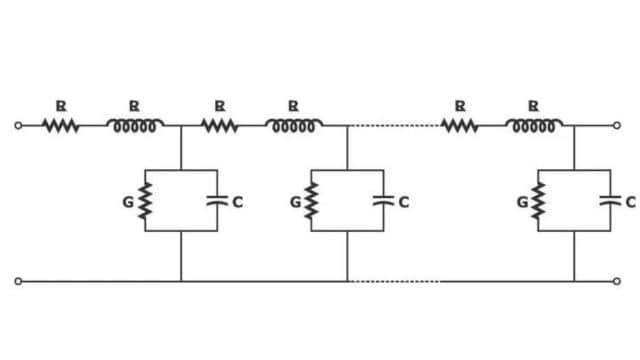
We can represent the ACSR conductor in a transmission line by using electrical values like resistance, inductance, capacitance, and conductance. In simpler terms, we create a model that captures how the ACSR conductor behaves electrically by looking at these specific parameters.
1. Resistance (R)
The resistance of a transmission line depends on three things: resistivity (how resistant the material is), length of the line (how long it is), and cross-sectional area (how thick it is). You can calculate the resistance using the formula: R = resistivity × length / cross-sectional area.
2. Inductance (L)
When electricity flows through a transmission line, it creates a magnetic field between the wires. We can represent this by calling it the inductance of the transmission line (L). In simpler terms, it’s like a measure of how much magnetic influence is created by the current moving through the wires.
3. Capacitance (C)
In a transmission line, the wires for each phase are kept apart by air, which acts as a dielectric (insulating material). When current flows through these wires, there’s a natural capacity for them to store electrical energy, and we call this capacitance (C). This capacitance becomes more noticeable in medium and long transmission lines but is usually not a big deal in short ones. Simply put, it’s like a measure of how much electrical energy can be stored between the wires due to the air in between them.
4. Conductance (G)
The imperfections in insulators can cause a small amount of current to leak through. We describe this leakage with the conductance parameter (G). In long transmission lines, this leakage effect is notable, but we usually ignore it when analyzing short and medium transmission lines. So, conductance is like a measure of how much current “leaks” through the insulators, but we only worry about it in long lines.
By using these four parameters the transmission line can be modeled as shown below.
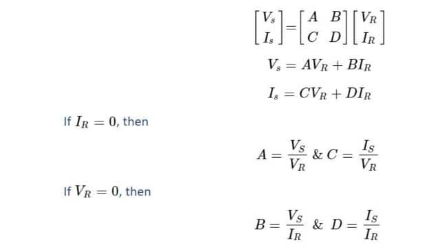
To understand and work with the transmission line, we use parameters like R (resistance), L (inductance), G (conductance), and C (capacitance). However, directly analyzing the circuit with these parameters can be tricky. So, to simplify things, we make some basic assumptions and introduce ABCD or transmission line parameters. Before diving into these models, it’s essential to have a basic understanding of these parameters. In simpler terms, we use ABCD parameters to make it easier to study and work with transmission lines by simplifying their representation.
Transmission Line Parameters or ABCD Parameters
If you have voltage (Vs) and current (IS) at the start of the transmission line (supplying end) and voltage (VR) and current (IR) at the end of the line (receiving end), you can express the relationship between them using the ABCD or transmission line parameters. In simpler words, it’s a way to describe how the voltage and current change from the beginning to the end of the transmission line.
Assumptions in Transmission Line Modelling
When we model a transmission line, we make a couple of basic assumptions:
- We assume the system is balanced, meaning everything is in equilibrium.
- We consider the network as a lumped system, which means we treat the resistance (R), inductance (L), capacitance (C), and conductance (G) as if they are concentrated in tiny parts of the network, making the analysis simpler. In simpler terms, we break down the complex network into smaller, more manageable pieces.
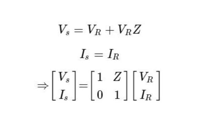
Modelling of Short Transmission Line
When we model a short transmission line, we can simplify things by ignoring the effects of capacitance and conductance since they are not significant for short lines. This allows us to draw a simpler equivalent circuit. In simpler words, for short transmission lines, we don’t need to worry much about capacitance and conductance, so we can represent the line more straightforwardly.
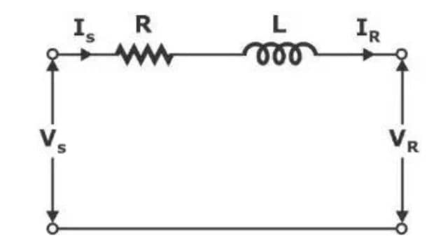
Z=R+jωL
From the circuit
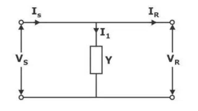
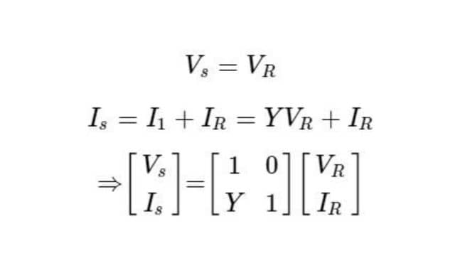
The above short transmission-line network can also be represented in the form of an admittance network as shown below.
VS = VR
Modeling of Medium Transmission Line
When looking at a medium transmission line, we focus on the effects of resistance (R), inductance (L), and capacitance (C), while neglecting the impact of conductance. In simpler terms, for medium transmission lines, we don’t worry much about conductance, so our analysis revolves around R, L, and C. There are three main methods to model medium transmission lines.
- Nominal T-network
- Nominal 𝜋-network
- End condenser network
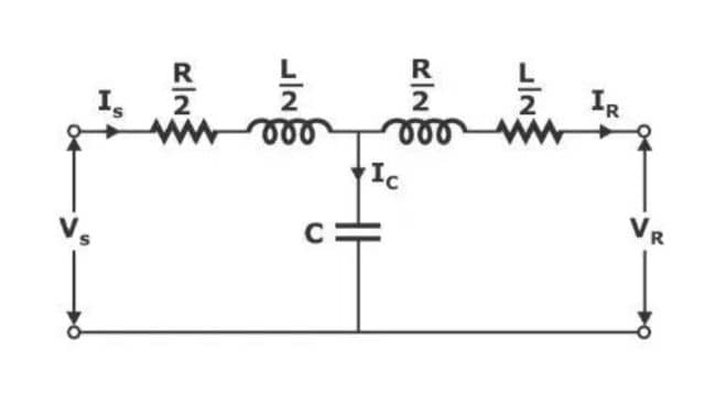
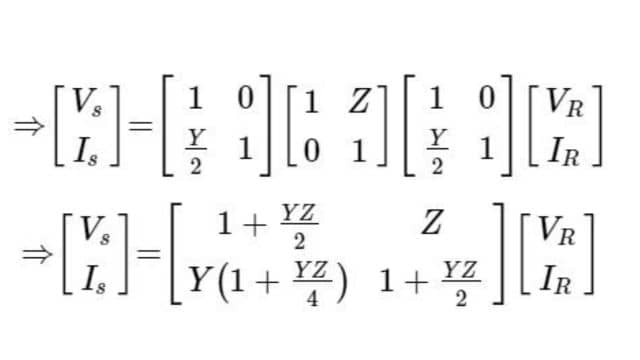
1. Nominal T-network
In the nominal T-network for a transmission line, we imagine splitting the line’s impedance into two equal parts. We then consider the entire capacitance of the transmission line as if it’s concentrated right in the middle. In simpler terms, it’s like breaking the line into two, and thinking of all the capacitance as being in the center of the line.
From now on, I’ll provide the ABCD parameter equations for each network directly. I assume you can understand them based on our previous discussions about short transmission lines. If not, you can refer to our lectures for a more detailed explanation. In simpler terms, I’ll give you the equations, and if you need more clarity, you can check the lectures for a deeper understanding.
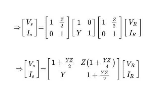
When we analyze using the T-network method, there might be some errors in our calculations because we assumed all the capacitance is concentrated in the middle of the transmission line. However, to reduce these errors, we can use the nominal π-network method. In simpler terms, the π-network helps minimize mistakes in our calculations that may arise from our assumptions about where the capacitance is located in the transmission line.
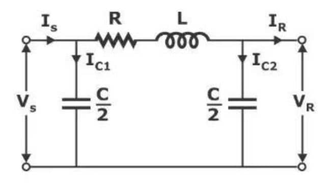
2. Nominal 𝝅-Network
In the nominal-π network, we distribute half of the capacitance at the supplying end and the remaining half at the receiving end of the transmission line. In simpler terms, we split the capacitance, putting part of it at the start and the rest at the end of the line.
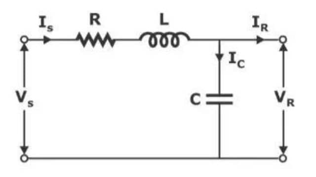
3. End Condenser Network
In the end condenser network, we imagine putting all the capacitance of the transmission line at the receiving end. In simpler terms, we consider the entire capacitance as if it’s located only at the end where the signal is received.
Modelling of Long Transmission Line
When we model a long transmission line, we need to consider all four parameters: resistance (R), inductance (L), capacitance (C), and conductance (G). The method for this modeling is quite detailed and lengthy, so I’m providing the result here. We can discuss it more thoroughly in our lectures for a clearer understanding. In simpler words, for long transmission lines, we take into account all the factors, and the method is a bit complex.
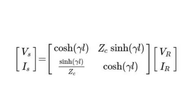
Where:
- γ=α+jβ=√(ZY) →propagation constant
- 𝛼→Attenuation constant
- 𝛽→Phase shift constantly
- l→Length of the transmission line
- Zc=√Z/Y →Characteristic impedance of the transmission line
Frequently Asked Questions (FAQs)
-
What are the 3 types of transmission lines?
Transmission lines: parallel lines, coaxial cable, stripline, microstrip. Higher frequency means shorter waves. Different lines carry signals efficiently at various frequencies.
-
What is the ABCD parameter?
ABCD parameters relate input voltage and current to output voltage and current in a network. They’re equations simplifying the analysis of electrical systems.
-
What is the full form of Z-parameters?
The full form of Z-parameters is “Impedance Parameters.”
-
Are all transmission lines 3-phase?
No, not all transmission lines are three-phase. Transmission lines can be single-phase or three-phase, depending on the specific requirements and characteristics of the electrical system they serve.
Read Also:
- Electrical Braking System
- Advanced Electric Drives Notes | Engineeringa2z
- Incandescent lamps | Types, Advantages, and Applications
- Difference Between AC and DC Welding


Leave a Reply