Table of Contents
Introduction
Circuit analysis is crucial in electrical engineering for designing circuits. The Laplace transform, created by Pierre-Simon Laplace in the late 18th century, is a helpful math tool. It simplifies the analysis of complex linear time-invariant systems in circuits.
Laplace Transform
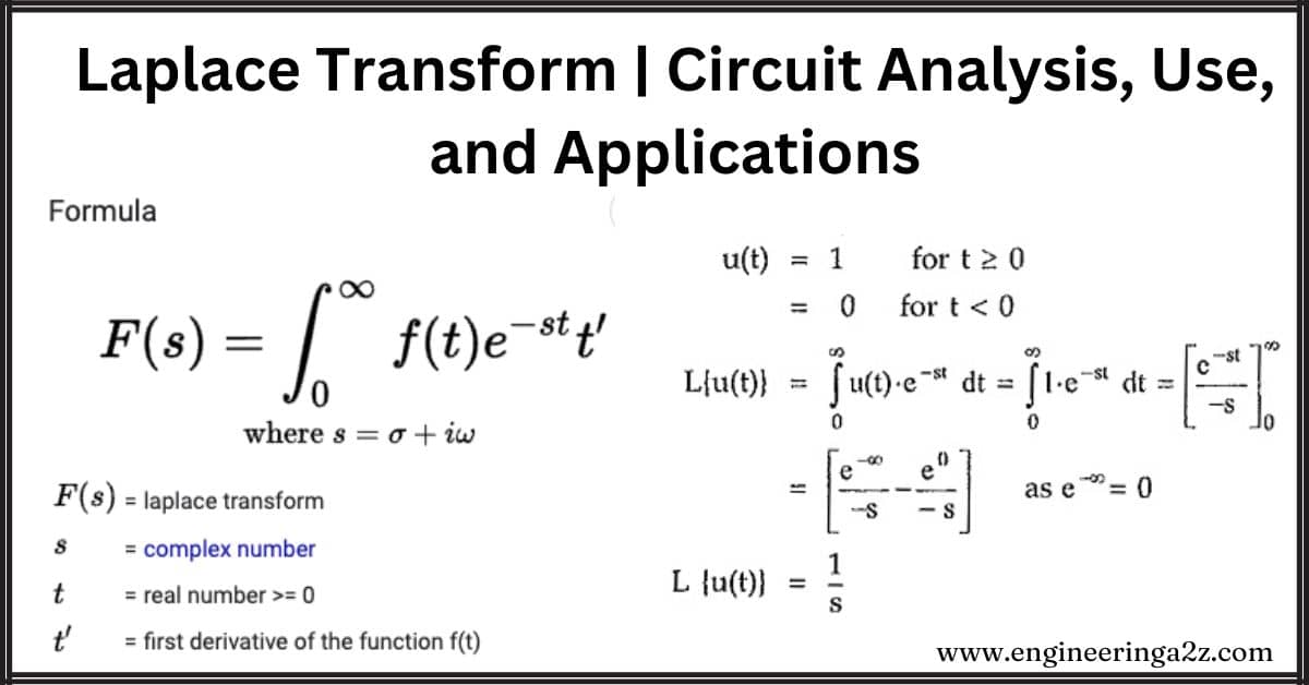
The Laplace transform is like a math tool that changes how we look at functions in time to understand them better in frequency. It’s useful for turning complicated equations into simpler ones, making it great for studying electrical circuits and similar systems.
Mathematical Representation of Laplace Transform:
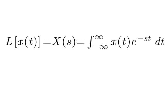
where x(t) is a time-domain function and is converted to frequency domain (X(s)).
Circuit Analysis using Laplace Transform
The Laplace Transform is a powerful math tool for solving complex circuit issues. It changes a circuit’s time-based view to a frequency-based one, making analysis easier. To solve a circuit with Laplace Transform:
- Write the circuit’s differential equation.
- Apply the Laplace Transform to that equation.
- Analyze the equations in the frequency domain (s-domain).
In circuits, key components are the Resistor (R), Inductor (L), and Capacitor (C). We’ll use Laplace Transform to analyze circuits with these components.
1. Pure Resistive Circuit
The image below represents a purely resistive circuit.
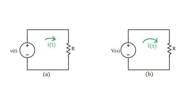
Applying KVL in Figure (a):
v(t) = i(t)R —— (1)
Taking the Laplace transform of equation 1:
V(s) = I(s)R —— (2)
Equation 2 represents the Laplace Transform of Equation 1.
This analysis shows that the resistance R stays the same in both time and frequency domains. Check out the Figure for the Laplace Transformed Circuit.
2. Pure Inductive Circuit
The image represents a purely inductive circuit.
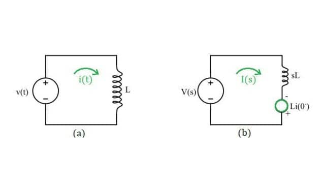
Applying KVL in Figure (a):

Taking the Laplace transform of equation 1:
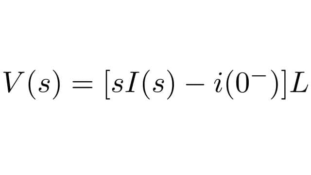
Here, i(0–) is the initial current flowing through the conductor. Equation 2 represents the Laplace Transform of Equation 1.
If the initial current flowing through the conductor is 0 then equation 2 will be:
V(s) = LsI(s) —— (2)
Hence, the above analysis shows that the inductor L in the time domain is converted to ‘SL’ in the frequency domain. Also, figure 2(b) shows the Laplace Transformed Circuit.
3. Pure Capacitive Circuit
The image represents a pure capacitive circuit.
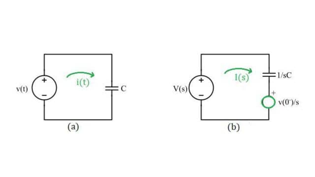
Applying KVL in Figure (a):
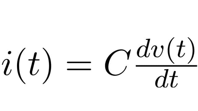
Taking the Laplace transform of equation 1:
I(s) = C(sV(s) – v(0–))
I(s) = sCV(s) – Cv(0–)
I(s) = sCV(s) – q(0–)
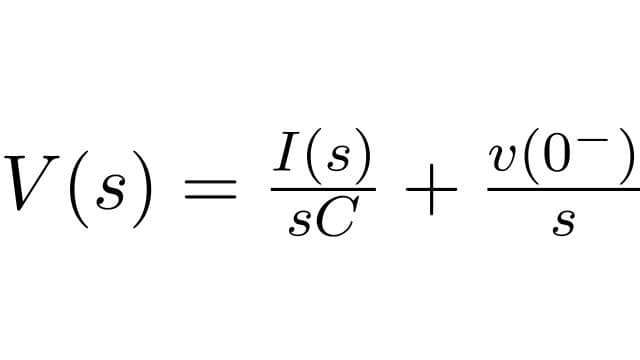
Here, v(0–) is the initial voltage across the capacitor. Equation 2 represents the Laplace Transform of equation 1.
If the voltage across the capacitor is 0, i.e., the capacitor is discharged then equation 2 will be:
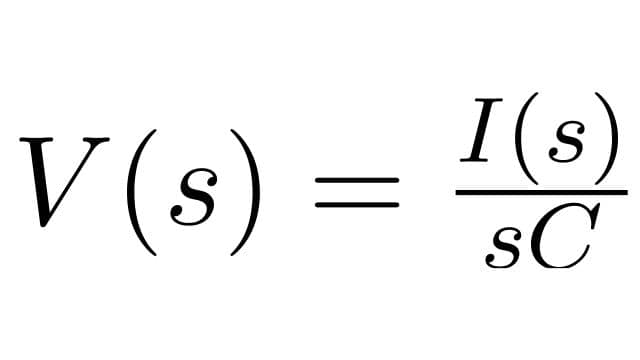
Hence, the above analysis shows that the capacitor C in the time domain is converted to 1/sC in the frequency domain. Also, figure 3(b) shows the Laplace Transformed Circuit.
Why We Use the Laplace Transform in Circuit Analysis?
- Simplifies Differential Equations:
- Challenge: It is hard to solve complex differential equations for circuits.
- Solution: Laplace Transform turns them into simpler algebraic equations, making them easier to work with.
- Frequency Domain Analysis:
- Benefit: Useful for understanding how circuits respond to different frequency parts of input signals.
- Application: Valuable in signal processing and filter design.
- Analysis of Time and Frequency:
- Advantage: Easily switch between time and frequency domains.
- Efficiency: Makes circuit analysis more efficient.
Advantages of Laplace Transform in Circuit Analysis
- Convolution Theorem:
- Benefit: Let us use the Convolution Theorem, making it easy to see how circuits respond to different input signals.
- Transient and Steady State Analysis:
- Use: Helps distinguish between transient (temporary) and steady-state (constant) responses in circuit analysis.
- Advantage: Simplifies the analysis of how circuits behave.
- Initial Conditions Handling:
- Benefit: Offers an intuitive way to handle initial conditions in circuit analysis.
- Simplicity: This makes it easier to describe the state of the circuit at time t=0 as they turn into constants in the s-domain.
- Impulse Response Analysis:
- Usefulness: The s-domain model makes it easy to analyze a system’s impulse response, which is crucial for understanding how a circuit reacts to sudden changes or input spikes.
- Stability Analysis:
- Application: Used to analyze the stability of feedback control systems, ensuring desired system performance.
Disadvantages of Laplace Transform in Circuit Analysis
- Limited Applicability to Nonlinear Systems:
- Challenge: Works best for linear systems, but not so great for analyzing circuits with nonlinear components like transistors and diodes.
- Result: Might lead to inaccurate analysis in such cases.
- Complexity of the Inverse Laplace Transform:
- Issue: While Laplace Transforms simplify analysis, going back from the s-domain to the time domain (inverse Laplace Transform) can be tricky.
- Need: Requires typical mathematical methods.
- Hard to Determine Initial Conditions:
- Difficulty: Figuring out the initial conditions for a circuit at time t=0 can be tough, especially if the circuit has been running for a long time or if the original conditions are unclear.
Applications of Laplace Transform in Circuit Analysis
- Control Systems:
- Use: Essential for analyzing and designing control systems.
- Application: Engineers rely on it to assess stability and efficiency and craft controllers meeting specific requirements.
- Signal Processing:
- Contribution: Aids in analyzing and manipulating data in the frequency domain.
- Application: Useful in signal processing tasks like image and audio processing, assisting in noise reduction and signal enhancement.
- Filter Design:
- Role: Used in creating filters for applications like audio processing and communication.
- Precision: Allows precise control over the bandwidth and cutoff frequency of filters through the Laplace transform.
Frequently Asked Questions (FAQs)
-
How is the Laplace transform used in circuit analysis?
Laplace transform simplifies circuit analysis by converting complex time-domain differential equations into manageable algebraic expressions in the s-domain, enabling easier evaluation of circuits’ behavior and responses.
-
What are the components of a Laplace circuit?
A Laplace circuit typically consists of resistors (R), inductors (L), and capacitors (C). The Laplace transform is applied to the circuit’s differential equations, transforming them into algebraic expressions in the s-domain for analysis and evaluation.
-
What are the basic functions of Laplace transform?
The basic functions in Laplace transform include exponentials, unit step functions, unit impulse functions, and sines/cosines. These functions, when transformed, simplify the analysis of linear time-invariant systems, making them valuable in circuit analysis and control systems engineering.
Read Also:
- Maximum Power Transfer Theorem | Formula, Proof, and, Limitations
- Superposition Theorem | Procedure, Limitations, and Applications
- Norton’s Theorem
- Reciprocity Theorem | Statement, Limitations, and Applications


Leave a Reply