Table of Contents
Introduction
In both DC and AC circuits, when you have a power source (like a battery or generator) connected to something that uses that power (like a lightbulb or a motor), you want to make sure that as much power as possible gets transferred to that thing using the least amount of energy.
In DC circuits (with a constant flow of electricity), it’s like having a resistor connected to a battery. For maximum power to go from the battery to the resistor, the resistor must have the same resistance as the battery.
In AC circuits (where electricity changes direction), it’s a bit more complex. Here, it’s about matching the load (what you’re powering) with the source (where the power comes from). To get the most power to the load from the AC power source, the load’s impedance (like resistance for AC) should match the source’s impedance, but it needs to be a special match called the complex conjugate.
In simpler terms, it’s like tuning a radio to the right frequency. When the load or resistor matches up just right with the power source, you get the most power efficiently transferred, just like tuning a radio to the right station for the clearest sound.
Maximum Power Transfer Formula
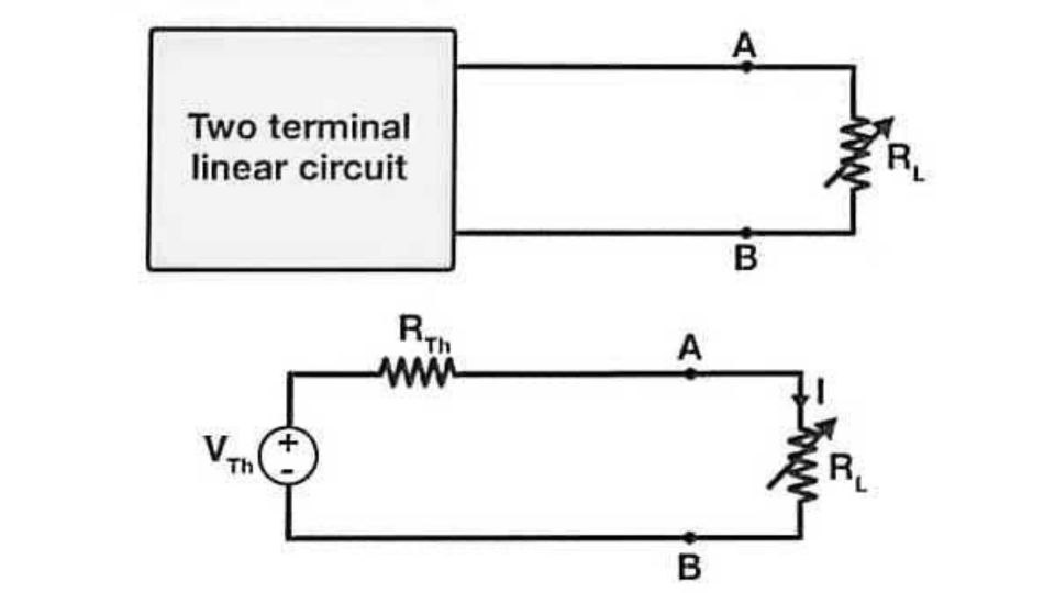
As shown in the figure, a DC source network is connected with variable resistance RL.
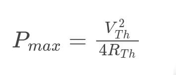
The fundamental Maximum Power Transfer Formula is:
Maximum Power Transfer Theorem Proof
The Maximum Power Transfer Theorem aims to figure out the value RL, which consumes maximum power from the source.
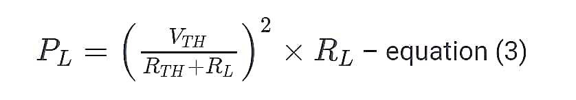
The power dissipated across the load resistance is given by,
PL = I2RL – equation (1)
Where PL is the power dissipated across the load resistance.
RL is the load resistance.
To derive the maximum power transfer theorem consider a DC network connected to the load resistance as shown in the figure above.
According to Thevenin’s theorem,
The current passing through the circuit is given by,
According to Thevenin’s theorem,
The current passing through the circuit is given by,
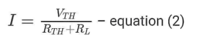
Where,
I- is the current passing through the circuit.
VTH is the Thevenin voltage source.
RTH is the Thevenin Resistance source.
RL is the load resistance.
From equation (1) and (2) we get,
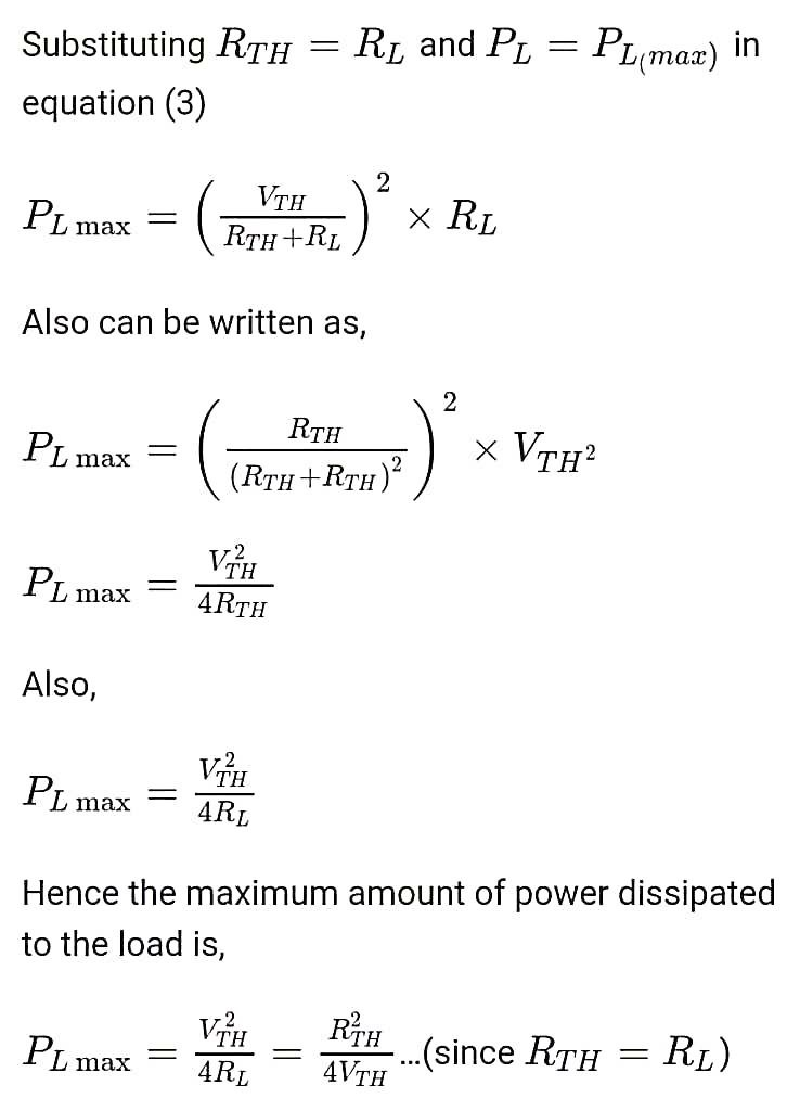
Value of Maximum Power Transfer
Limitations of Maximum Power Transfer Theorem
- Limited Applicability: Works only with linear and bilateral networks.
- Efficiency Constraint: The maximum efficiency achievable is 50%.
- Unsuitability for Power Systems: Not suitable for analyzing or optimizing power systems.
Applications of Maximum Power Transfer Theorem
- Optimizing Efficiency in Non-Linear Networks: Even in non-linear setups, the theorem helps find the best efficiency for a specific load.
- Matching Speakers and Amplifiers in Sound Systems: Big sound systems use this concept to make sure the speakers and amplifiers work together efficiently.
- Car Engines and Batteries: When the starter motor and battery reach equal values, they hit peak power, aiding the car’s startup.
- Solar Applications: It’s used in solar setups to extract the most power possible from panels, maximizing their output.
Frequently Asked Questions (FAQs)
-
What is the formula for maximum output power?
Maximum output power in an electrical circuit: Pmax = V2source / 4Rsource
achieved when load resistance matches the source’s internal resistance. -
What are impedance matching and maximum power transfer?
Impedance matching optimizes signal transfer by aligning source and load impedances, reducing reflections. Maximum power transfer occurs when load impedance matches source impedance, yielding peak power transmission efficiency.
-
Why do we need maximum power transfer?
Maximum power transfer ensures efficient energy utilization, minimizing losses. It’s vital in various systems like electronics, power transmission, and communication to optimize performance and reduce wasted energy.
-
What is the Thevenin’s theorem?
Thevenin’s theorem simplifies complex electrical circuits into a voltage source and a series resistance, aiding analysis and understanding of circuit behavior.
Read Also:
- Circuit Theorem | Thevenin’s Theorem
- Norton’s Theorem
- Basic Electrical Engineering | Engineeringa2z
- Fundamentals of Electric Circuits Solutions 6th Edition PDF
- B.Tech – MDU Previous Year Question Papers Download


Leave a Reply