Table of Contents
Circuit Theorem
Circuit theorems are fundamental principles and mathematical techniques utilized in the analysis and solution of electrical circuits. Derived from the laws and principles of electrical circuit theory, such as Ohm’s law, Kirchhoff’s laws, and network topology, these theorems enable engineers and scientists to simplify intricate circuits, determine circuit parameters, and analyze circuit behavior. They offer a systematic approach that significantly simplifies circuit analysis.
One of the fundamental theorems is Ohm’s Law, which states that the current passing through a conductor is directly proportional to the voltage applied and inversely proportional to the resistance. Another crucial set of laws is Kirchhoff’s Laws, comprising Kirchhoff’s Current Law (KCL) and Kirchhoff’s Voltage Law (KVL). KCL asserts that the sum of currents entering a node is equal to the sum of currents leaving it, while KVL states that the sum of voltages around any closed loop in a circuit is zero. Lets Discuss the Norton’s Theorem :-
Introduction to Norton’s Theorem
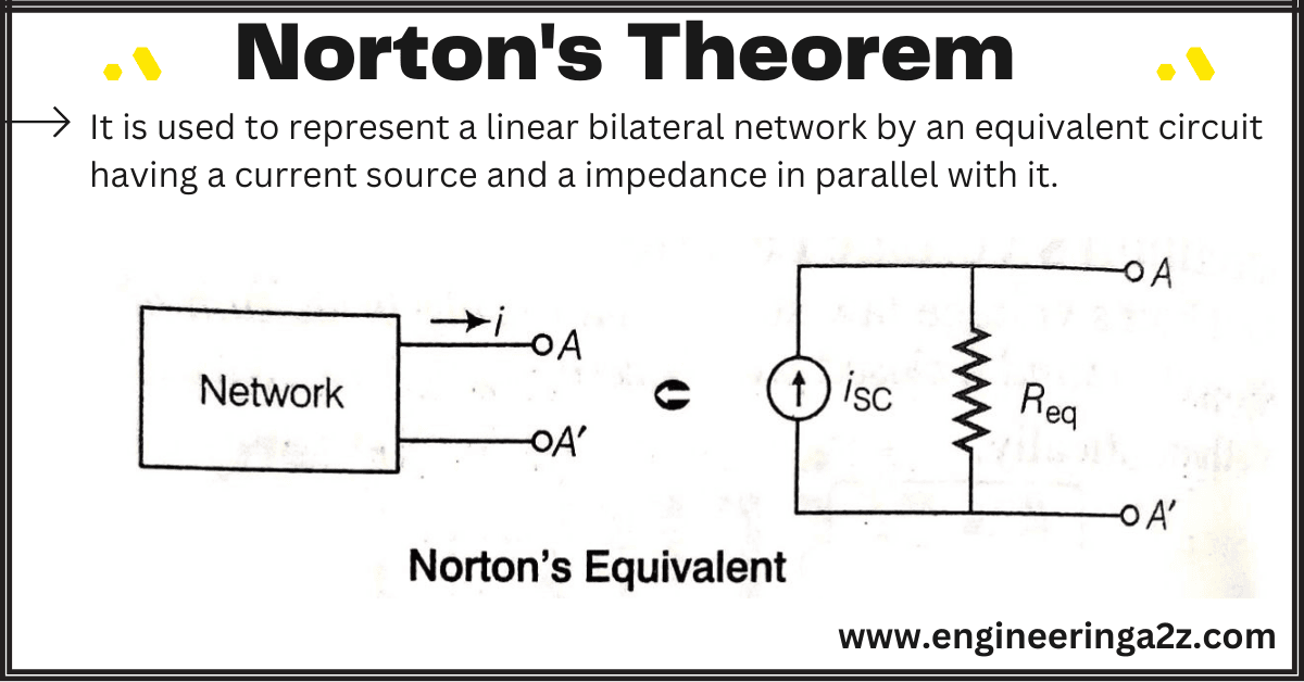
According to this theorem, the current passing through a resistance between any two terminals of the network can be determined by replacing the entire network by an equivalent constant current source and a parallel resistance. It is used to represent a linear bilateral network by an equivalent circuit having a current source and a impedance in parallel with it as explained.
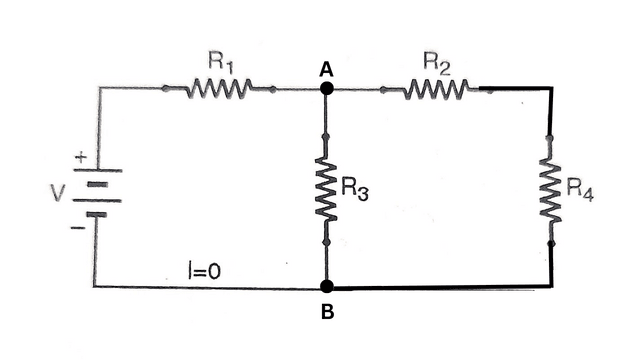
Norton’s Current: It is the curret supplied by the source which will pass through two selected terminals, when they are short circuited. It is denoted by Isc. Its value is Isc = V /R1 Amp.
Norton’s Resistance: It is generally known equivalent resistance of the network as viewed from two selected terminals, when all the emf sources are replaced by their internal resistances, and current sources by open circuit as shown in Fig. 4.66. It is denoted by Ri. The value of Ri viewed from the terminals A and B is given :
Ri = R1 X (R2+ R4)/R1 + (R2+ R4)
Therefore, according to Norton’s theorem, a linear active R-L-C network which contains one or more independent or dependent voltage and current sources can be replaced by a single current source is in paralled with the impedence.
Procedure to solve a circuit by using the Norton’s theorem:-
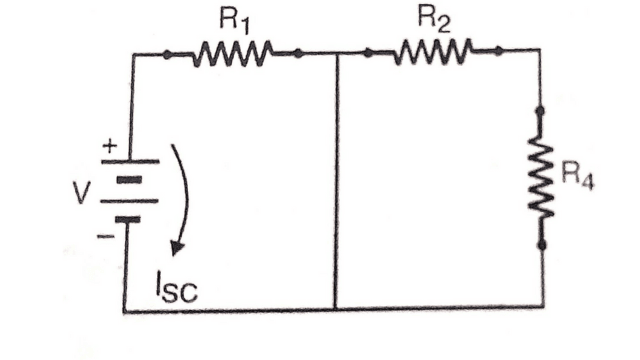
- Remove the resistance if any across two given points and short circuit them.
- Calculate the current which will flow through the circuit. It is called Norton’s current and is written as Isc.
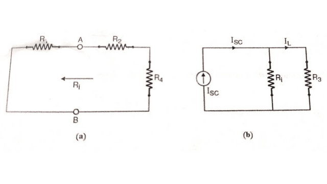
- Find the resistance Ri of the whole network as viewed from terminals AB, into the circuit when all the voltage sources have been removed by short circuits and replaced by their internal resistances. It is same as Thevenin’s Theorem.
- The Norton’s resistance and load resistance RL, are connected in parallel across current sources as shown in Figure.
- Then the load current IL is determined from following relation:
IL = ISC x Ri / Ri+R3
Example using Norton’s Theorem
Using Norton’s Theorem, determine the current in 20 Ω resistor in the network as shown in figure?
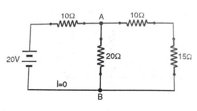
To determine the current in 20Ω resistor the following steps should be followed:
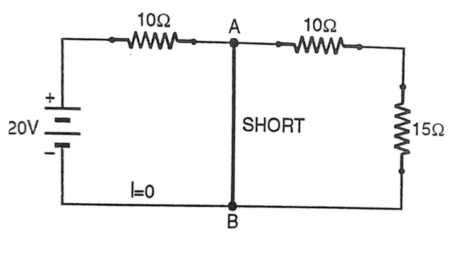
- Remove the 20Ω resistor and short circuit the two terminals as shown in below figure . Determine the current Isc, which is limited by only 10Ω resistor.
Isc = 20/10 =2A (Here voltage is 20V and effective resistance is 10Ω.)
- The voltage source is replaced by its internal resistance and redraw the circuit as shown.
- Keeping the selected terminals A and B open circuited, Ri. Norton’s resistance or resistance of the network as seen from terminals A and B is as under.
- Calculation Of Ri = Total Resistance across AB on Right side (10+15)=25Ω and on left side of AB is 10Ω. These two are in parallel with each other 25Ω||10Ω =25*10/25+10 =7.14Ω
- The Norton’s current source is shown in Figure.
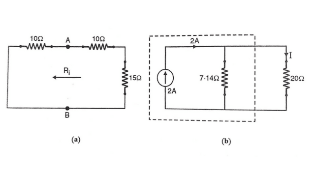
- Current flowing through 20 Ω resistor is
I= Isc x Ri/Ri+RL ( Use this formulae for calculating Current )
I= 2 x 7.14 /7.14+20
=0.526 A Ans.
Frequently Asked Question:- FAQs
-
What is Dual network of Norton’s Theorem
Dual network of Norton’s Theorem is Thevenin’s Theorem.
-
What is Nortorn’s Current?
It is the short circuit current across the load resister RL in the given circuit.
-
How is Norton’s theorem different from Thevenin’s theorem?
Thevenin’s theorem and Norton’s theorem are two complementary techniques used to simplify complex circuits. Thevenin’s theorem allows us to simplify a circuit into a single voltage source and a resistor, while Norton’s theorem simplifies the circuit into a single current source and a resistor.
-
Can Norton’s theorem be applied to nonlinear circuits?
No, Norton’s theorem is only applicable to linear circuits.


Leave a Reply