Table of Contents
Introduction
Two-port networks simplify complex electrical circuits. They represent components like transmission lines and transformers, as well as electronic ones like transistors. This overview explains two-port network parameters, how to calculate them, and conditions for symmetry and reciprocity, aiding in network analysis.
What is a Two-Port Network?
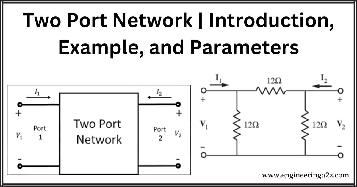
A port is a pair of terminals where current enters one and exits the other. Components like resistors, inductors, and capacitors are examples of one-port networks, where electrical interactions occur at a single pair of terminals.
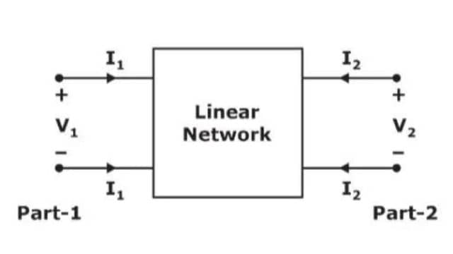
A two-port network has two pairs of terminals, here named port 1 and port 2. V1 and V2 represent the voltages at these ports, while I1 and I2 represent the currents flowing through the respective ports.
Two Port Network Example
A few examples of Two Port Network are:
- Filters,
- Small-signal models for transistors
- Matching networks,
- Transmission lines,
- Transformers,
Two Port Network Parameters
In a two-port network, you can provide input to any port and extract output from any port. The parameters used to describe such networks are called two-port network parameters. There are six sets of these parameters, named Z, Y, T, T’, h, and g parameters, involving voltage (V) and current (I).
Z Parameters
In a two-port network, with I1 and I2 as inputs and V1 and V2 as outputs, the Z parameters describe the relationship:
- V1 = Z11 * I1 + Z12 * I2
- V2 = Z21 * I1 + Z22 * I2
Z11 is found by making port 2 an open circuit when I2 is 0, and Z12 is found by making port 1 an open circuit when I1 is 0. Similarly, Z21 and Z22 are obtained. These parameters are called impedance parameters or Z parameters. They represent the ratio of output voltage to input current and are measured in Ohms (Ω).
- A two-port network is symmetrical if Z11 equals Z22.
- A two-port network is reciprocal if Z12 equals Z21.
Y Parameters
In a two-port network, considering V1 and V2 as inputs and I1 and I2 as outputs, the Y parameters describe the relationship:
- I1 = Y11 * V1 + Y12 * V2
- I2 = Y21 * V1 + Y22 * V2
Y11 is found by making port 2 a short circuit when V2 is 0, and Y12 is found by making port 1 a short circuit when V1 is 0. Similarly, Y21 and Y22 are obtained. These parameters are called admittance parameters or Y parameters, representing the ratio of output current to input voltage, measured in mhos (℧).
- A two-port network is symmetrical if Y11 equals Y22.
- A two-port network is reciprocal if Y12 equals Y21.
T Parameters
In a two-port network, with V2 and I2 as inputs and V1 and I1 as outputs, the T parameters (Transmission parameters) describe the relationship:
- V1 = AV2 – BI2
- I1 = CV2 – DI2
Here, A, B, C, and D are constants obtained under specific conditions:
- A = V1/V2 when I2 is 0
- B = -V1/I2 when V2 is 0
- C = I1/V2 when I2 is 0
- D = -I1/I2 when V2 is 0
A and D have no units, while B and D have units of ohms (Ω) and mhos (℧), respectively. The ABCD parameters are also known as T parameters. A and C are obtained by making port 2 an open circuit, while B and D are obtained by making port 2 a short circuit.
- A two-port network is symmetrical if A equals D.
- A two-port network is reciprocal if AD – BC equals 1.
T’ Parameters
In a two-port network, with V1 and I1 as inputs and V2 and I2 as outputs, the T’ parameters (Inverse Transmission parameters) describe the relationship:
- V2 = A’V1 – B’I1
- I2 = C’V1 – D’I1
Here, A’, B’, C’, and D’ are constants obtained under specific conditions:
- A’ = V2/V1 when I1 is 0
- B’ = -V2/I1 when V1 is 0
- C’ = I2/V1 when I1 is 0
- D’ = -I2/I1 when V1 is 0
A’ and D’ have no units, while B’ and D’ have units of ohms (Ω) and mhos (℧), respectively. The A’B’C’D’ parameters are also known as Inverse Transmission parameters or T’ parameters. A’ and C’ are obtained by making port 1 an open circuit, while B’ and D’ are obtained by making port 1 a short circuit.
- A two-port network is symmetrical if A’ equals D’.
- A two-port network is reciprocal if A’D’ – B’C’ equals 1.
h Parameters
In a two-port network with I1 and V2 as inputs and V1 and I2 as outputs, the h parameters (Hybrid parameters) describe the relationship:
- V1 = h11 + h12V2
- I2 = h21I1 + h22V2
Here, h12 and h21 are unitless, and the units of h11 and h22 are ohms (Ω) and mhos (℧), respectively. The h parameters can be obtained under specific conditions:
- h11 = V1/I1 when V2 is 0
- h12 = V1/V2 when I1 is 0
- h21 = I2/I1 when V2 is 0
- h22 = I2/V2 when I1 is 0
Two h parameters, h11, and h21, can be found by making port 2 a short circuit, and the other two, h12 and h22, can be found by making port 1 an open circuit.
- A two-port network is symmetrical if h = 1, i.e., h11h22 – h21h12 = 1.
- A two-port network is reciprocal if h12 equals -h21.
g Parameters
In a two-port network with V1 and I2 as inputs and I1 and V2 as outputs, the g parameters (Inverse Hybrid parameters) describe the relationship:
- I1 = g11V1 + g12I2
- V2 = g21V1 + g22I2
Here, g12 and g21 are unitless, and the units of g11 and g22 are mhos (℧) and ohms (Ω), respectively. The g parameters can be obtained under specific conditions:
- g11 = I1/V1 when I2 is 0
- g12 = I1/I2 when V1 is 0
- g21 = V2/V1 when I2 is 0
- g22 = V2/I2 when V1 is 0
Two g parameters, g11, and g21, can be found by making port 2 an open circuit, and the other two, g12 and g22
Two g parameters, g11, and g21, can be found by making port 2 an open circuit, and the other two, g12 and g, can be found by making port 1 a short circuit.
, can be found by making port 1 a short circuit.
- A two-port network is symmetrical if g = 1, i.e., g11g22 – g12g21 = 1.
- A two-port network is reciprocal if g12 equals -g21.
Frequently Asked Questions (FAQs)
-
What is meant by the two-port network?
A two-port network is an electrical network or circuit with two pairs of terminals, allowing independent input and output variables. It’s commonly used to model complex systems in a simplified manner.
-
What is the use of two-port?
A two-port is used to model and analyze complex electrical systems, simplifying their representation. It aids in understanding and designing circuits, facilitating the study of signal flow and interactions.
-
What is the formula for 2 ports?
The general representation of a two-port network involves four variables: V1 and I1 as input voltage and current, and V2 and I2 as output voltage and current. Different parameter sets like Z, Y, T, h, and g parameters express the relationships between these variables.
-
How many numbers is a port?
A port in a two-port network consists of a pair of terminals through which electrical signals enter and exit. A two-port network has two such ports, providing input and output connections.
Read Also:
- Maximum Power Transfer Theorem | Formula, Proof, and, Limitations
- Superposition Theorem | Procedure, Limitations, and Applications
- Norton’s Theorem
- Reciprocity Theorem | Statement, Limitations, and Applications


Leave a Reply