Table of Contents
Electrical Braking Definition
This is the method in which kinetic energy of the motor is converted into electric energy and dissipated as heat in a resistance and returned to supply. Note that electric brake cannot stop a motor and ultimately mechanical brakes are used. However electric braking reduces the stopping time and also wear and tear.
Characteristics of a good braking system
- It should be reliable.
- It should be quick.
- In case of failure of the brakes the whole system should come to rest.
- There should be suitable arrangement to store the K.E of the moving parts.
Types of Electric Braking
- Plugging
- Rheostatic Braking
- Regenerative Braking
1. Plugging
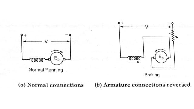
This is the simplest method in which connection of the armature are reversed. As the motor moves in reverse direction, mechanical brakes are instantly applied and the motor stops, consequently the supply to the motor is disconnected automatically
Plugging in DC Shunt Motor
The connection of the armature is reversed so that the motor tends to rotate in reverse direction, thus providing the necessary braking effect. When the motor stops, the supply to the motor is automatically cut off, otherwise the motor will start rotating in reverse direction.

Normal running Braking : Note that field connection remain unchanged. In order to limit the current to safe value, a variable resistance is inserted in the circuit while changing connections.
Plugging in DC Series Motor
The plugging in series motor is done as in the case of a shunt motor. It should be noted that, during braking, in addition to the K.E of the motors (series as well as shunt) being dissipated in the resistance, some energy is also drawn from the supply so there is a wastage of energy.
Also when the motor is driving a load, the load will exert an additional breaking corque so total braking torque on the motor is due to braking plus due to load.
Plugging in Induction Motor
If any two phases of a 3 phase induction motor are interchanged, the direction of rotation of the motor is reversed. This produces a braking torque. Supply to motor should be cut off when the motor stops, otherwise the motor will start rotating in the reverse direction.
Plugging in Synchronous Motor
In synchronous motor fitted with Damper Winding, braking effect is produced when their dc excitation is reversed due to eddy currents induced (in the damper winding).
2. Rheostatic Braking
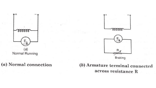
This is also called as Dynamic braking. In this method armature of the running motor is disconnected from the supply and is connected across a variable resistor. However a field winding remains connected with the supply. The motor acts a generator sending a large current through the resistance. This causes energy of the rotating rotor dissipated in the resistor. As a result the motor stops.
Rheostatic Braking in DC Shunt Motor
The rheostatic braking in dc shunt motor is shown in figure. The braking torque can be adjusted by adjusting the variable resistor. By decreasing R, braking torque can be increased and vice versa. This method is used hoists and elevators in which motor needs starting, stopping and reversing frequently.
Rheostatic Braking in DC Series Motor
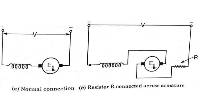
The Rheostatic breaking in series motor is shown in Figure. It is same as in case of shunt motor. The motor ta generator, for this it is necessary that the total resistance in the circuit is less than the critical resistance, so that the generator may be self excited.
Rheostatic Braking in Induction Motor
The stator is disconnected from the supply and connected to dc supply. When the rotating conductors cut the of the steady flux of dc supply an emf is induced in them which provides braking effect.
Rheostatic Braking in Synchronous Motor
The field excitation is maintained and the motor after disconnecting from the supply is connected to resistance in star or Delta, It now acts as alternator and losses are dissipated in the resistor
3. Regenerative Braking
In this braking the motor is run as a generator and K.E of the motor is converted into electrical energy which is returned back to the supply. This braking is used in DC Traction.
Regenerative Braking of DC Shunt Motor
In this method field is disconnected from the supply and field current is increased by increasing excitation from the supply source. The emf will exceed the supply voltage and motor will feed energy to the supply.

Regenerative Braking of DC Series Motor
For this 2 or 3 auxiliary windings are provided along with the main winding. During normal running these windings are placed in parallel and for breaking in series with the main winding.
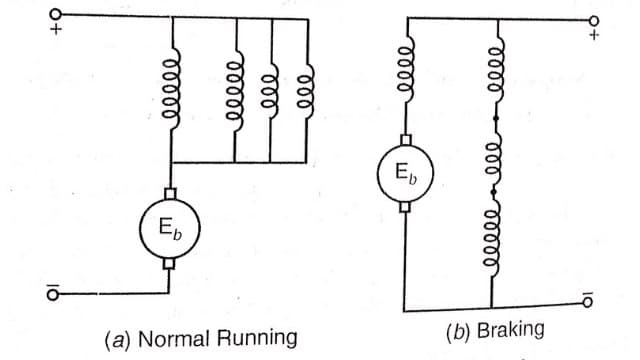
The motor works as a differential compound motor and braking effect is produced.
Regenerative Braking of Induction Motor
When an induction motor runs at a speed above synchronous, it runs as induction generator and returns power to the supply. Regenerative breaking is not successful in induction motor.
Regenerative Braking in Synchronous Motor
The regenerative breaking is not used in synchronous motors.
Frequently Asked Questions (FAQ)
What do you mean by electrical braking?
Electrical braking is the method in which kinetic energy of the motor is converted into electric energy and dissipated as heat in a resistance and returned to supply. Note that electric brake cannot stop a motor and ultimately mechanical brakes are used.
What type of brake system is used in electrical vehicle?
Mostly we uses regenerative braking in electrical vehicle and DC traction. In this braking the motor is run as a generator and K.E of the motor is converted into electrical energy which is returned back to the supply.
What are the types of electrical braking?
The types of electrical braking are plugging (counter-current braking ), rheostatic ( dynamic braking), regenerative braking which are applicable to the usual types of electric motors.
What is regenerative braking?
Regenerative braking is the braking in which the motor run as a generator and Kinetic energy of the motor is converted into electrical energy which is returned back to the supply. This braking is used in DC Traction.
Read Also :
- No load or Blocked Rotor Test on Three Phase Induction Motor
- Three Phase Induction Motor | Construction & Working Principle
- Basic Electrical Engineering | Engineeringa2z


Leave a Reply