Table of Contents
Introduction
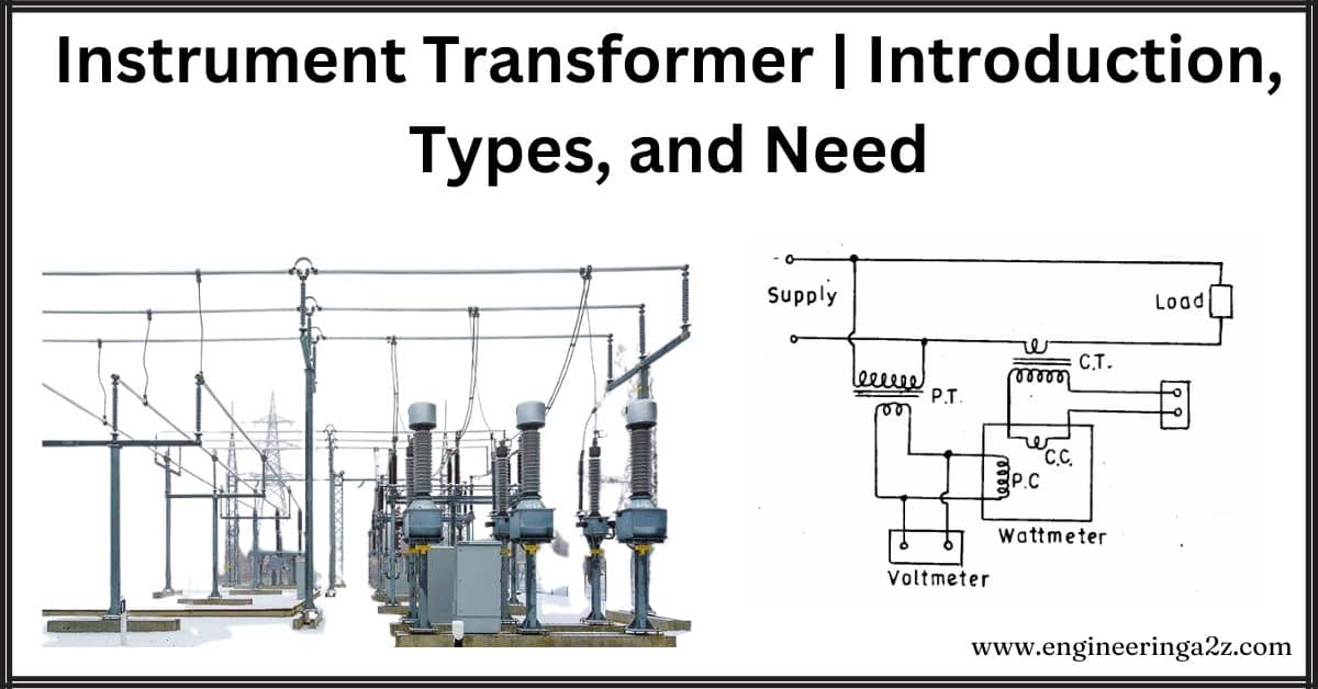
Instrument transformers are like magic glasses for electrical systems. They help us measure things like voltage and current accurately, even though these things can be super high and tricky to handle. Imagine trying to measure the voltage in your house with a tiny meter – it’s just not safe or practical. So, we use instrument transformers to “shrink” those high voltages and currents down to safer levels that our regular meters can handle. This makes it much easier and safer to measure what’s going on in the electrical system, helping to keep everything running smoothly and protected.
What is an Instrument Transformer?
An instrument transformer is like a special tool used in electricity to make it easier and safer to measure big things like voltage and current. It works by taking the high levels of electricity in power lines and making them smaller, so regular measuring instruments can handle them without getting overwhelmed. It’s kind of like using a magnifying glass to see tiny details better – except instead of making things bigger, it makes them smaller and safer to measure.
Types of an Instrument Transformer
There are two types of instrument transformers, and they are namely:
- Current transformer (C.T)
- Potential transformer (P.T), also known as the voltage transformer.
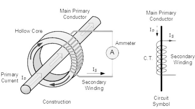
1. Current Transformer (C.T.)
- Purpose: Current transformers (CTs) reduce the high current in power systems to levels that can be measured by small ammeters (like a 5A ammeter).
- Connection: The primary winding of the CT, which has few turns or sometimes a solid bar, is connected in series with the power circuit.
- Secondary Winding: The secondary winding has many turns and is directly connected to the ammeter.
- Operating Condition: The secondary operates almost like a short circuit because the ammeter has very low resistance.
- Safety Measures: To prevent high voltage buildup across the secondary winding:
- One terminal of the secondary is grounded to reduce the risk of insulation breakdown and protect operators from high voltage.
- Before disconnecting the ammeter, a switch ‘S’ shorts the secondary to avoid voltage buildup.
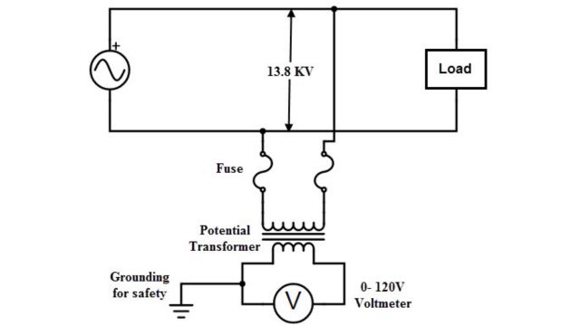
2. Potential Transformer (P.T.)
- Purpose: Potential transformers (PTs) lower the high voltage in power systems to levels that can be measured by small voltmeters (like a 110-120 V voltmeter).
- Connection: The primary winding of the PT, which has many turns, is connected across the power line (usually between one line and the earth).
- Operating Condition: The secondary winding, which has few turns, is directly connected to the voltmeter. Since the voltmeter has high resistance, the secondary operates almost like an open circuit.
- Safety Measures: To maintain operator safety and prevent voltage hazards:
One terminal of the secondary of the PT is grounded to keep the secondary voltage safe relative to the earth.
Errors in the Current Transformer
Two errors occur with the current transformer; they are namely:
- Ratio error
- Phase angle error.
1. Ratio Error
It’s a measure of how much the transformer’s output differs from the ideal output. We calculate it by comparing the actual turns ratio (Kn) with the rated turns ratio (R).
2. Phase Angle Error
Ideally, the angle between the primary and secondary current should be 180°, but in reality, it’s slightly less due to factors like magnetizing current. We denote this difference as (180° – θ), where θ represents the phase angle error.
Causes of Errors in Current Transformer
- Losses in the core: Some energy is lost as heat in the core of the transformer.
- Losses in winding resistance: Energy is lost as heat when electricity flows through the wires of the transformer.
- Flux leakage: Some magnetic energy doesn’t fully transfer from the primary winding to the secondary winding.
- Core saturation: When the core is overloaded with too much magnetic energy, it can’t handle it all, leading to inaccuracies in the transformer’s operation.
Reduction of Errors in Current Transformer
- Using High-Permeable Materials: By using materials like CRGO steel, nickel-ferrous alloy, and silicon steel stampings for the core, we can minimize energy loss in the transformer’s core.
- Reducing Air Gap: Keeping the space between the primary and secondary windings as small as possible helps prevent magnetic energy from escaping, reducing inaccuracies in the transformer’s operation.
Advantages of an Instrument Transformer
- Usage: Small rating measuring instruments (e.g., 5 A, 110-120 V) are used to measure large voltage and current of AC power systems.
- Standardization: Instrument transformers allow for standardization of measuring instruments, reducing costs and facilitating easy replacement of damaged instruments.
- Electrical Isolation: Instrument transformers provide electrical isolation between high-voltage power circuits and measuring instruments, reducing insulation requirements and ensuring operator safety.
- Multiple Connections: Several measuring instruments can be connected to a single transformer, simplifying connections to the power system.
- Low Power Consumption: Measuring and protective circuits operate at low voltage and current levels, resulting in low power consumption.
Need for an Instrument Transformer
- Problem: Voltmeters and ammeters of high ratings needed for commercial metering are impractical due to size, cost, and operational difficulties.
- Challenge: Extending the range using multipliers and shunt connections is costly and inaccurate.
- Solution: Instrument transformers step down high currents and voltages to levels that can be measured with smaller, more affordable instruments.
- Benefits: Allows measurement with instruments of moderate size and cost, ensures operator safety by providing isolation from high voltage circuits.
- Examples: Enables measuring high voltages like 132 kV with a 110 V instrument, and high currents like 1000 A with a 5 A ammeter.
Frequently Asked Questions (FAQs)
-
What is an Instrument Transformer?
A transformer that is used to measure electrical quantities like current, voltage, power, frequency and power factor is known as an instrument transformer. These transformers are mainly used with relays to protect the power system.
-
What are instrument transformers used for?
Instrument transformers are used to step down high voltage and current levels in electrical systems for safe and accurate measurement.
-
What is the function of CT and PT?
Current transformers (CTs) step down high currents for safe measurement by ammeters. Potential transformers (PTs) step down high voltages for safe measurement by voltmeters. Both ensure accurate readings and operator safety.
-
What is the instrument transformer in a substation?
An instrument transformer in a substation is a device used to step down high voltage and current levels for safe and accurate measurement by meters and protective relays.
Read Also:
- Parallel Operation Of 1 Phase/ 3 Phase Transformers
- Output Equation of Transformer
- Three Phase Transformer | Construction & Working
- Transformer | Construction, Working Principle | Advantages & Disadvantages
- Explain Construction and Working of Autotransformer


Leave a Reply