Table of Contents
Introduction
HVDC converters introduce both AC and DC harmonics which are injected into the AC system and DC line respectively. There are several problems associated with the injection of harmonics and these are listed below:
- Telephone interference
- Extra power losses and consequent heating in machines and capacitors connected to the system
- Overvoltages due to resonances
- Instability of converter controls, primarily with an Individual Phase Control (IPC) scheme of firing pulse generation
- Interference with ripple control systems used in load management.
AC filters are invariably used to filter out AC harmonics which are critical. These filters are of bandpass (tuned) or high pass type and also supply reactive power. DC smoothing reactor along with DC filters performs the function of filtering DC harmonics. While most of the filters used in converter stations are passive filters using inductors and capacitors, active filters based on VSC have been introduced since 1993 in conjunction with passive filters. At present, there are 14 active filters on the DC side and one active filter on the AC side.
In addition to the harmonics that cause telephone interference, the harmonics at the carrier and radio frequencies are also generated by the converters and may require suitable filters. The harmonic generation and the various types of filters used in converter stations are described in this chapter. The criteria and some of the design aspects are also presented.
Generation of Harmonics
1. Characteristic Harmonics
The characteristics of harmonics are always present even under ideal operation balanced AC voltages, symmetric three-phase network, and central pulses. In the converter analysis, the DC is assumed to be constant. In this case, there are harmonics in AC of the order:
h = np ± 1,
where p is the pulse number, n is any integer. The harmonics in the converter DC voltage are of the order:
h = np
When the smoothing reactor is of finite impedance, there are harmonics in the DC also of the order given by. The AC harmonics, in this case, are still of the order defined, although their magnitudes will be different with the presence of the ripple in DC.
2. Calculation of Characteristic AC Harmonics
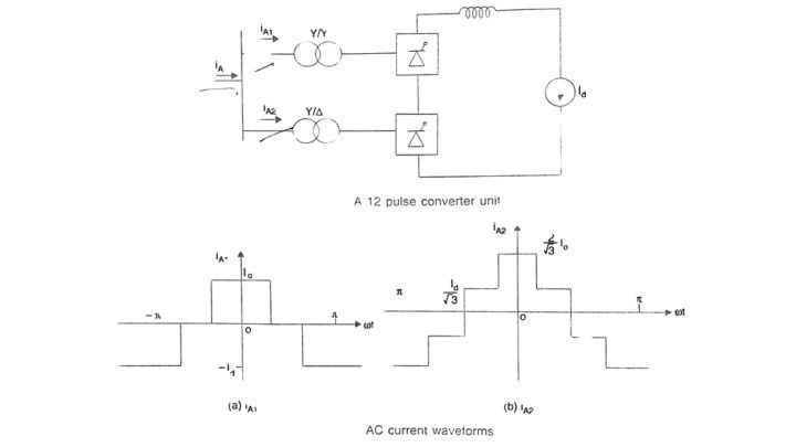
Consider a 12-pulse converter unit shown in Fig. Neglecting overlap, the waveforms of currents in and in are shown in Fig. For convenience, the ordinate axis (corresponding to oof (0) is chosen such that the waveform has even symmetry. The waveforms also have half-wave symmetry so that even harmonics are zero. Hence, we can express 1A1 as:
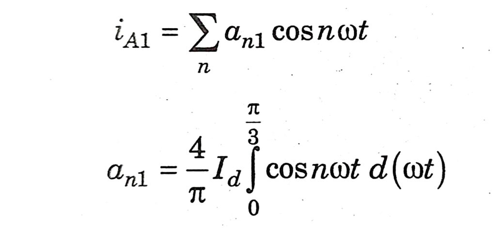
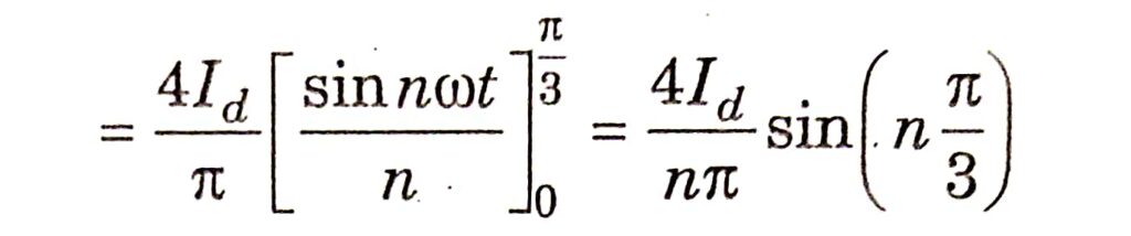
It is obvious an1 = 0 for triplen harmonics. Also, an1 = -2√3 / nπ. Id for n = 6k – 1 and an1 = 2√3 / nπ. Id for n = 6k + 1 where k is a positive integer.
The current iA2 can be expressed as:
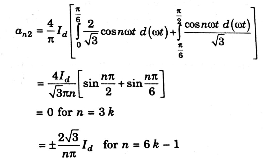
The positive sign applies to odd values of k and the negative sign applies to even values of k. Similarly, it can be shown that:
an2 = ∓ 2√3 / nπ. Id for n = 6k + 1
The negative sign applies to odd values for k and the positive sign applies to even values of k. The current I is given by:
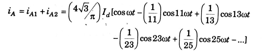
From the above expression, it can be observed that:
- I10 = (2√6) / π) Id
- Ih0 = (I10 / h)
where I10 and Ih0 are rms values of the fundamental component and harmonic of order ‘h The second subscript ‘o’ indicates that the overlap angle u is assumed to be zero.
When the overlap angle is non-zero, the expression for Ih, is given by:
Ih = Iho [A2 + B2 -2AB cos(2α+u)1/2] / cosα -cosδ
Where A = sin(h+1) . u/2 / h+1 , B = sin(h-1) . u/2 / h-1 , δ = ( α + u)
The above expression is valid for u ≤ 60°. For higher values of the overlap angle, the expression given by can still be used if, α, u, and δ are replaced by α’, u’, and δ’ where
α’ = α – 30°, u’ = u + 60°, δ’ = δ + 30°
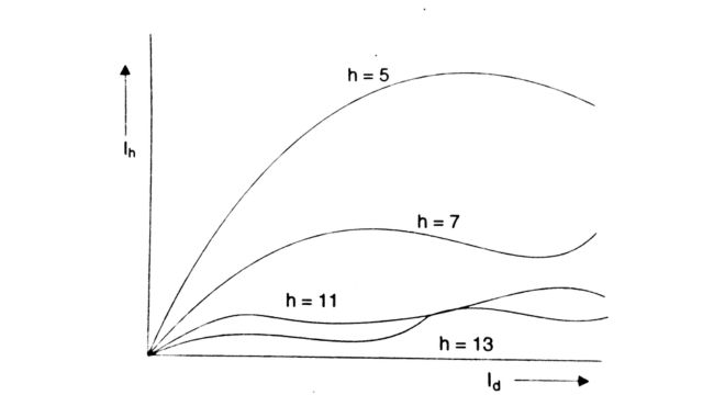
The effect of the overlap angle is to prevent steep changes in the AC. This implies that 1, is smaller than Iho. For example, for α = 15°, u = 25°, the 11th and 13th harmonic currents are reduced to about 0.25Iho.
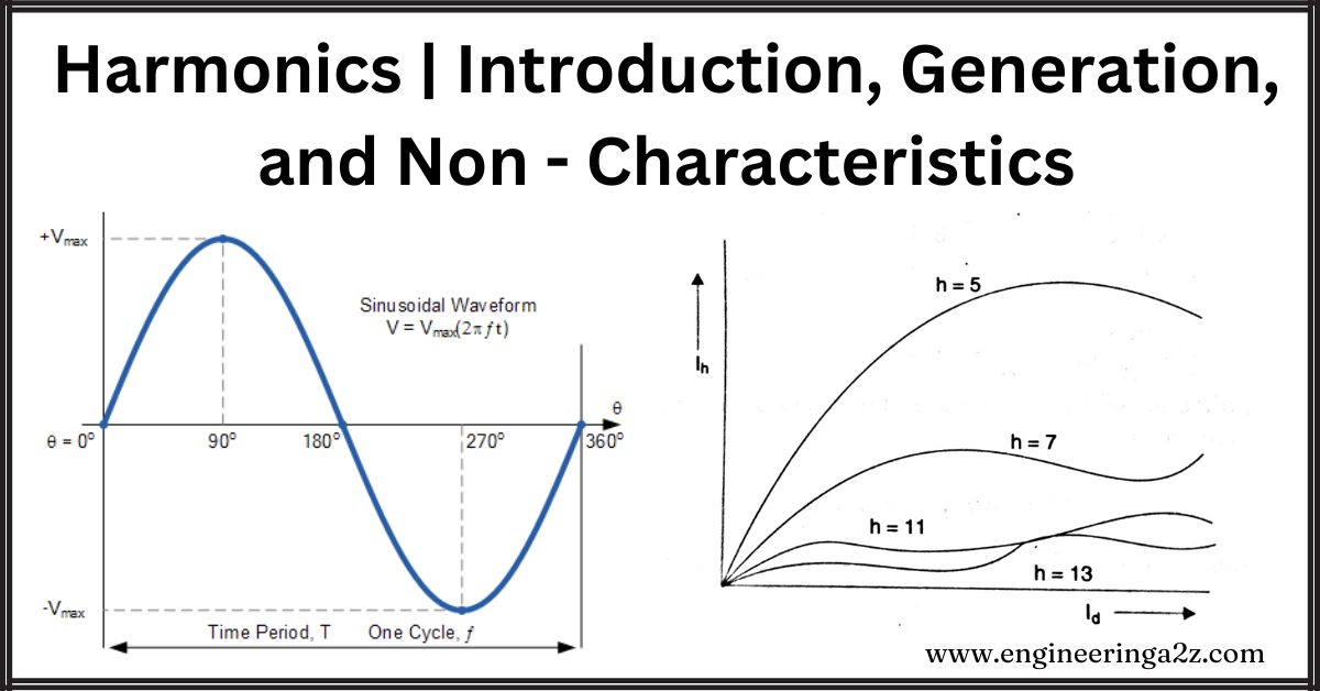
The magnitudes of the characteristic harmonics are also functions of the load current. This is shown in Fig
3. DC voltage harmonics
From the Fourier analysis of the DC voltage waveform, we can obtain
Vh = Vdo [C2 + D2 -2CD cos(2α+u)]1/2 / √2
where
C = (cos[(h + 1) . u/2] / h + 1 , D = (cos[(h – 1) . u/2 / h – 1
Non-characteristic Harmonics
The harmonics of the order other than the characteristic harmonics are termed as non-characteristic. These are due to (an imbalance in the operation of two bridges forming a 12-pulse converter:
- (i) Imbalance in the operation of two bridges forming a 12-pulse converter
- (ii) Firing angle errors
- (iii) Unbalance and distortion in AC voltages and
- (iv) Unequal transformer leakage impedances.
The harmonics produced due to the first cause are termed residual harmonics. These are mainly due to the difference in the firing angles in the two bridges which lead to unequal cancellation of the harmonics of order 5, 7, 17, 19, etc. The unequal leakage impedances of the two converter transformers feeding the two bridges also lead to residual harmonics.
The last three causes can lead to the generation of triplets and even harmonies and their analysis is complex.
1. Effect of Firing Angle Errors
It is convenient to neglect overlap in the analysis. The errors in the firing angles can be due to the jitter or the nature of the control system. The equidistant pulse control scheme ideally, has no inherent errors except due to the jitter.
To study the effect of firing angle errors, we will simplify the analysis by considering a single Graetz bridge fed from a star/star-connected transformer. We consider the error εj as the delay in the firing of the valve from the instant corresponding to the desired value of the firing angle a.
There is no loss of generality in assuming the firing error for valve 1 is zero as the analysis applies to steady-state conditions, where it is assumed that the waveform is periodic with the fundamental frequency of o. Thus, there are five independent parameters ε2, ε3, ε4, ε5 and ε6.
To illustrate the analysis, we will consider an example with the following data:
ε3 = ε5 = 0, ε2 = ε4 = ε6 = ε
The waveform of the phase currents is similar to the waveform of iA1 shown in Fig. Το analyzes the waveforms, we can consider them as the sum of two waveforms-one ideal with no firing errors and the other that represent the effect of firing errors. Thus, we define
- ia (t) = ia0 (t) + Δ ia (t)
- ib (t) = ib0 (t) + Δ ib (t)
- ic (t) = ic0 (t) + Δ ic (t)
where ia0, ib0, and ic0 represent ideal waveforms neglecting firing angle errors. For the data given, the waveforms of Δ ia, Δ ib, and Δ iac.
Note that Δ ia = 0 except when – (2π) / 3 ≤ θ ≤ – (2π) / 3 + ε and (2π) / 3 ≤ θ ≤ (2π) / 3 + ε, θ = ωt
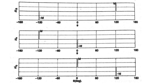
Similarly Δ ib = 0 except when – (2π) / 3 ≤ θ ≤ – (2π) / 3 + ε and 0 ≤ θ ≤ ε and Δ ic = 0 except when 0 ≤ θ ≤ ε and (2π) / 3 ≤ θ ≤ (2π) / 3 + ε.
To analyze these let us consider the complex Fourier Series for a function fit), defined by
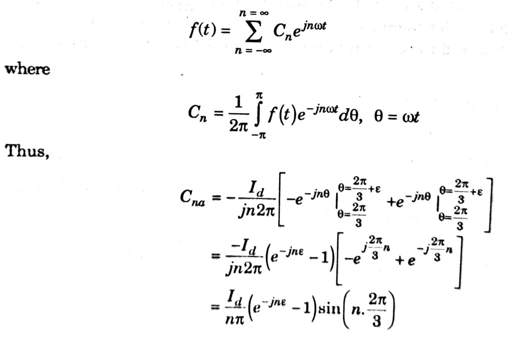
Similarly, it can be shown that
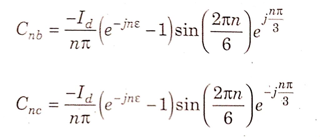
It is obvious that for Cna = Cnb = Cnc = 0 for n = 3k, where & is a positive integer. It can be shown that for n = 2, the current components form a negative sequence and for n = 4, the current components form a positive sequence. In general, the sequence is negative when n = 3k – 1 and positive when n = 3k + 1 where k is an integer. It can also be shown that the firing angle errors also affect the characteristic harmonics and the fundamental (positive sequence) current components. The fundamental component (peak value), for small values of e is given by:
I1peak = 2√3 / π. Id cos(ε/2)
The magnitude (peak value) of the non-characteristic harmonie is given by:
In = √3Id sin (nε / 2) / nπ = √3Id / 2π. ε = I10 ε / 2
The approximation applies for nε / 2 < 30°. This shows that the magnitudes of all the non-characteristic harmonics are identical for all values of n for which the approximation applies. For n < 30°, the harmonic distortion in the current due to non-characteristic harmonics alone with ε = 2°, is more than the distortion introduced by the characteristic harmonies for a 12-pulse converter. Thus, there is no significant advantage in increasing the pulse number beyond 12.
The major source of firing angle errors in modern converter stations is due to the ripple in the current feedback signal and not due to the equipment. The tolerance in the firing pulses does not exceed ± 0.2°
In twelve pulse converters, it is necessary to operate at equidistant pulse control in a steady- state to eliminate residual harmonics. This implies that the delay angle for each bridge is identical (when the voltages are balanced). This involves increased reactive power consumption which can be reduced by having independent control of bridges. However, this is not desirable as the harmonic generation is increased while trying to reduce the reactive power consumption.
2. Effect of Unbalanced Voltages
The presence of the negative sequence component in the AC voltage shifts the zero crossing of the commutation voltages. An individual phase control (IPC) system, introduces firing angle dissymmetry and results in non-characteristic harmonics. With a 5% negative sequence voltage, the third harmonic current generated can be as large as 5% of the fundamental component.
With the EPC firing scheme, this is avoided. However, if the smoothing reactor is finite, there will be a DC harmonic of second order which will generate an AC harmonic of third order.
Frequently Asked Questions (FAQs)
-
What do you mean by harmonics?
Harmonics are additional frequencies present in an electrical system, typically multiples of the fundamental frequency, caused by nonlinear loads and can lead to undesirable effects like voltage distortion.
-
What is the principle of harmonics?
The principle of harmonics, often referred to in physics and music theory, is based on the idea that when a vibrating object produces sound, it doesn’t just produce a single frequency (or pitch). Instead, it generates a series of frequencies that are integer multiples of the fundamental frequency.
-
What causes harmonics in AC systems?
Harmonics in AC systems are caused by nonlinear loads like electronic devices, which distort the sine wave, generating frequencies that are multiples of the fundamental frequency.
-
What are harmonics examples?
Examples of harmonics include the overtones produced by musical instruments, the distortion in electrical systems caused by nonlinear loads, and the resonance frequencies of vibrating objects.
Read Also:
- DC Breakers | Characteristics, Types, and Applications
- Instrument Transformer | Introduction, Types, and Need
- Potential Transformer | Construction, Working, and Errors
- Distribution Systems | Classification and Challenges
- Electrical Cable | Components, Types and Application


Leave a Reply