Table of Contents
Criteria of Design
The harmonics in the DC voltage across the converter contain characteristic and non-characteristic orders. These harmonics result in current harmonics in DC lines and cause noise in telephone circuits.
The harmonic current generated in the line can be computed from the knowledge of harmonic voltage sources at the converters, smoothing reactor, DC filter, and line parameters. The harmonic current varies with the distance (from the converter station) along the line.
The effectiveness of the DC filter is judged by one of the following criteria:
- Maximum voltage TIF on DC high voltage bus
- Maximum induced noise voltage (INV) in millivolts/km in a parallel test line one kilometer away from the HVDC line
- Maximum permissible noise to ground in dBrnc in telephone lines close to HVDC lines.
The use of the TIF criterion does not take into account the effects of coupling between the telephone line and the HVDC line. It also does not consider the standing wave phenomenon of the various harmonic currents along the DC line and the characteristics of the telephone line, such as balance and shielding.
The test line method has been used for designing HVDC filters for the Pacific Intertie Project in the Western USA. The Induced Noise Voltage (INV) computed is the longitudinal voltage along the test line and establishes a norm for a specific system. According to Bell Telephone Standards (BTS), the permissible total longitudinal noise voltage is 54.8 mV. This permissible voltage assumes a 50 dB balance in the telephone line. This implies that the transverse voltage induced in the telephone line is 1/102.5 = 1/316 times the longitudinal voltage. The permissible induced noise voltage is 0.178 mV.
This is based on the criterion, that the acceptable noise (according to BTS) must not exceed 20 dBrne that is 20 dB above the reference level of 10-12 W (1 pico watt). Thus, the permissible noise power is 10-10 W. Not more than half of this (0.5 x 10⁻¹⁰ W) should be from any one source. Since telephone lines are usually terminated in an impedance of 600 ohms, transverse noise voltage (C-message weighted) corresponding to the noise power of (0.5 x 10⁻¹⁰ W) is
√PR=0.173 mV
To use criterion independent of a particular system, the equivalent disturbing current method is now widely used. The induced noise on a communication circuit near an HVDC line is computed from

where n is the order of the harmonic, and N is determined by the system frequency. An upper limit of 5000 Hz corresponds to N = 83 in a 60 Hz network and N =100 in a 50 Hz network. k is the number of conductors in the line. Ijn is the nth harmonic current in the jth conductor. Zmjn is the mutual impedance between the telephone line with jth conductor at nth harmonic impedance depending on the earth’s resistivity. Ksn is the shielding factor and Pn is the weighting factor at nth harmonic.
The harmonic current I jn is a function of the distance from the sending or receiving end. Typically, the current is obtained as a superposition of two components-one due to the source voltages at the sending end and the second, due to the voltages at the receiving end. If the phase angles of the harmonic voltages at the two ends of the line are not known exactly, a root sum of the squares of the currents at the two ends is used. Thus we have,

We assume that the disturbing effect (on the telephone line) can be approximated by a current on a single conductor geometrically located between the conductors on the DC line. Neglecting variations in the mutual impedance as a function of j, we can obtain the expression for the induced noise voltage on nearby a telephone line as
Vg = [ ΣNn = 1 (InPnKsnZmn)2]1/2
where I2n = I2ns = I2nr
Definition of equivalent disturbing current
Assuming that the majority of the wire-line circuits susceptible to induced noise will be shielded cable, either crossing or close to the DC line, we can assume KsnZmn as independent of the frequency and we can express it as
Vg = Ie. Ze
where Ze is the effective average value of KsnZmn typically calculated at 1000 Hz, with C-message weighted noise calculations. Ie is defined as
Ie = [ ΣNn = 1 (InPn)2]1/2
Ie is termed as the equivalent disturbing current and represents current at a single frequency (typically, 1000 Hz) which has the same disturbing effect. Ie can be determined by the DC system design. For the chosen DC line routing, Ze can be determined by analysis of the routing of the communication circuits. The basic advantage of using the concept of Ie is to decouple the studies required to design the DC filters from studies involved in inductive coordination.
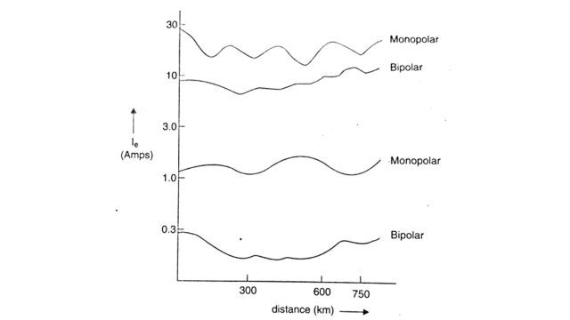
The specification Ie, determines the DC filter design. A value of Ie = 270 mA (C-message weighted) has been used in the USA. This specification is equivalent to the specification of 10 mV/km longitudinal INV used at Pacific Intertie (Ie = Vg / Zm where Zm is calculated at 0.0370 ohm/km). A sample profile of Ie with and without DC filters is shown in Fig for a specific HVDC link.
Passive DC Filters
Both tuned and damped passive filters have been used for DC filters. Back-to-back (BTB) HVDC links and those using cable systems do not have DC filters as induced noise is not an issue. The first HVDC scheme to use DC filters is the Sardinia link which has both cable and overhead line sections. Unlike in AC filters, the size of the filters does not depend on the reactive power requirements as this is not an issue with DC lines. The design is aimed (primarily) at reducing the filtering costs while meeting the specifications on the Ie (equivalent disturbing current).
The factors that affect the design of passive DC filters are given below:
- (1) Mixed cable/overhead line systems- usually have more than one natural resonance frequency. DC filters, if used, should consider the possibility of overvoltages due to line resonance. Sardinia, Hokkaido-Honshu, and Skagarrek schemes are examples of mixed cable/overhead line systems.
- (2) Modes of operation-Although bipolar mode of operation is used most of the time, monopolar ground return operation under extremely detuned conditions is the worst scenario to be considered. The monopolar metallic return mode results in a dB noise level compared to the worst case whereas the bipolar (unbalanced) mode has a -9 dB noise level (compared to the worst case).
- (3) DC line resonance overvoltages-HVDC line with smoothing reactors and DC filters has a natural first resonance at a low frequency (45-75Hz). If the line is resonant at the fundamental frequency, any continuous malfunction such as misfires can cause serious overvoltages. Smoothing reactor and/or DC filter parameters need to be changed to overcome this problem. While this may not always be feasible, it has been claimed that HVDC control systems can reduce such overvoltages. Overhead line or mixed cable and overhead line systems may have resonance frequencies corresponding to second and fourth harmonic. The excitation at these frequencies due to AC system faults can cause overvoltages. Although DC filters cannot significantly change the resonance frequencies, they can be designed to reduce the magnification level.
- (4) Overvoltages due to DC line faults- The overvoltages on the healthy pole during monopolar ground fault are affected by the line termination. High-pass damped filters are most effective in reducing the overvoltages by presenting resistive termination. Even line surge capacitors reduce the terminal overvoltages compared to those at the midpoint of the line. Limiting line and terminal overvoltages is an important consideration in the selection of the type and size of DC filters.
Presence of triplen harmonics in DC voltage
Although the classical theory does not predict the presence of triplen harmonics in the DC voltage (the smallest characteristic harmonic with a Graetz bridge is of order six), measurements of DC harmonics have disclosed the occurrence of triplen harmonics of magnitudes that cannot be explained by factors such as unbalance, firing angle errors, tolerances in the leakage impedances, etc. This has led to the development of a three-pulse model to explain the phenomenon. The cause for triplen harmonics was predicted to be the presence of stray capacitances inherent in converter transformers, bushings, etc.
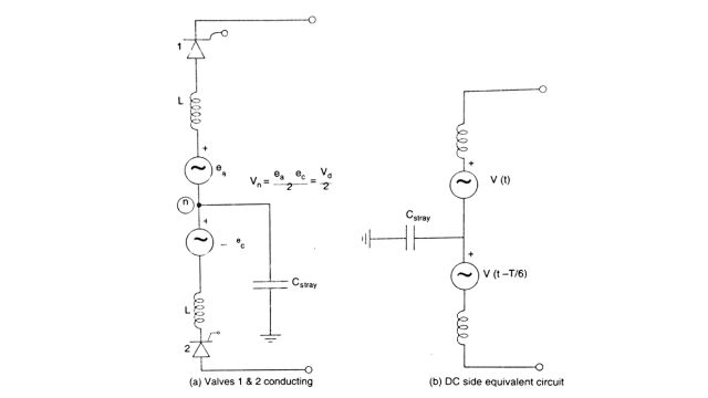
A Graetz bridge is a series connection of two valve groups. Each valve group can be modeled as a three-pulse converter. When the neutral point is not grounded there is no path for the flow of triplen harmonic currents. It can be easily seen that the neutral point voltage is not zero, but a third harmonic voltage (see Fig. (a) for the equivalent circuit when 2 valves in a bridge, say 1 and 2 are conducting) which has a magnitude of half the line to line voltage (ea – ec). If there are stray capacitances to the ground, triplen harmonic currents can flow in the ground path. The DC side equivalent circuit for a Graetz bridge is shown in Fig. (b). The analysis for a 12-pulse converter is also presented. The implications of the presence of triplen harmonics are the following.
- (1) Without a neutral bus capacitor, the telephone interference levels are several times (10-30) those calculated ignoring stray capacitances,
- (2) While a neutral bus capacitor can decrease the level of ground currents of all triplen harmonics, this may not be sufficient. DC filters with sufficiently low impedance at the troublesome triplen harmonics will be required. The filter impedances at the characteristic harmonics must also be considerably lower than what is predicted by the classical analysis. The resulting DC filters can become both large and complex with multiple tuned frequencies.
The authors claim that the utilities are specifying extremely low disturbing current criteria which may not be required for the problem of telephone interference.
Active Filters
Active filters were considered for DC filtering to meet the stringent requirements from power utilities in limiting telephone interference. The use of passive filters alone can increase the costs substantially. In 1991 a test installation was established at the Lindome station of Konti-Skan HVDC link. The first commercial active DC filter was installed in 1993 at the Skagerrak-3 HVDC intertie followed by Baltic Cable HVDC link in 1994. In India, active filters were installed at the Chandrapur-Padghe link in 1998.
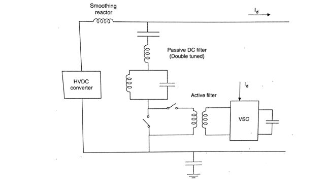
The active filter used in DC filtering is a hybrid active filter that is an active filter in series with a passive shunt filter. The configuration of the DC active filter is shown in Fig. Here, a double-tuned filter (for 12th and 24th harmonic) is connected in series with a VSC-based active filter. IGBT devices are used as switches in the VSC with Pulse Width Modulation (PWM). The transformer provides galvanic separation between the VSC and the HVDC line. It also helps in raising the voltage injected to the desired level.
The control strategy of the active filter is to inject the required harmonic voltages of appropriate magnitudes and phase angles to cancel the harmonic currents flowing in the line. At the Chandrapur-Padghe line, active filters are installed at both stations, each filter connected in series with the passive filter (12/24). The active filter is designed to operate in the range of 350-2500 Hz. There are four active filters in all. The use of an active filter replaced an additional passive filter-branch in each pole compared to a purely passive solution. The disturbing current was found to be 170 mA in the bipolar mode of operation, carrying a full load of 1500 MW.
Carrier Frequency and RI Noise
HVDC converter stations can produce high levels of electrical noise in the carrier frequency band from 20 kHz to 490 kHz. They also generate radio interference (RI) noise in the mega Hertz range of frequencies. However, converters are usually located in buildings that are effectively shielded against electromagnetic radiation. Hence the contribution due to direct radiation from valves can be neglected. The radiation from the switchyard can predominate over that produced by DC lines. Effective PLC-RI filters are necessary to minimize the impact of the noise and eliminate of interference with power line carrier communication.
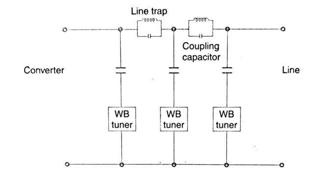
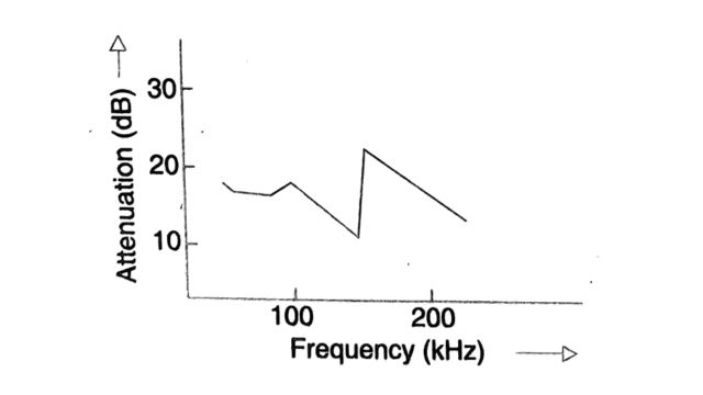
The configuration of a PLC/RI filter is shown in Fig. The actual attenuation of the noise by the filter must be above the curve shown in Fig.
The problem of interference to carrier systems is primarily from the turn-on of the valves in a converter which results in the discharge of stray and other capacitances in the converter station. The analysis of interference problems involves :
- (i) Determination of the magnitude of the noise produced by the converter valves,
- (ii) Coupling between the noise source and the carrier systems,
- (iii) Methods of reducing the coupling to avoid harmful interference.
Measurements and study of the carrier frequency noise result in the following conclusions:
- (1) The conducted converter valve noise magnitude is generally higher than the ambient corona noise in the AC switchyard. It is also higher than the corona noise on the AC and DC transmission lines.
- (2) The differences in these levels are more at the lower frequencies.
Frequently Asked Questions (FAQs)
-
What is a DC filter?
A DC filter is an electronic circuit or device designed to remove or reduce direct current (DC) components from an alternating current (AC) signal, often used in power supplies or audio systems.
-
Which filter is used for pure DC?
A capacitor-input filter is commonly used for achieving pure DC by smoothing out the rectified AC voltage in power supply circuits, effectively removing ripple and producing a steady DC output.
-
What is a rectifier filter?
A rectifier filter is a circuit component or arrangement used to convert alternating current (AC) to direct current (DC) while minimizing fluctuations or “ripple” in the output voltage.
-
What is meant by pure DC?
Pure DC refers to a direct current (DC) signal that is free from any fluctuations or variations, maintaining a constant voltage level over time. It lacks any alternating current (AC) components or ripple, making it stable and consistent for electronic applications.
Read Also:
- Electrical Cable | Components, Types and Application
- Distribution Systems | Classification and Challenges
- Transmission Line | Introduction, Classification, and Modelling
- Parallel Operation Of 1 Phase/ 3 Phase Transformers


Leave a Reply