Table of Contents
Introduction
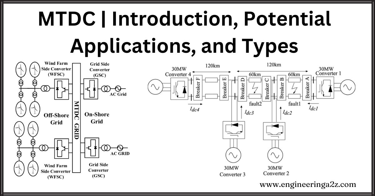
HVDC transmission systems designed and operated so far are point-to-point systems with two terminals (converter stations). A multiterminal DC (MTDC) system has more than two converter stations, some operating as rectifiers and others as inverters. The simplest way of building an MTDC system from an existing two-terminal system is to introduce tappings. Parallel operation of converters and bipoles can also be viewed as multi-terminal operations.
Unlike in AC systems, extending two terminal systems to multiterminal systems is not trivial. The complexities of control and protection increase considerably, and HVDC breakers are generally required in MTDC systems.
In recent times, with the growth in HVDC transmission, there could be more than one converter in proximity feeding the same load area. The operational issues of such Multi-Infeed DC (MIDC) systems are similar to those of MTDC systems. Hence, MIDC systems are also discussed in this chapter. With recent advances in the emerging technology of VSC-HVDC transmission, the application of MTDC systems is becoming more attractive than before.
Potential Applications of MTDC Systems
Apart from tapping of power from the existing two-terminal systems, there are three specific areas of applications for MTDC systems. These are listed below:
- Bulk power transmission from several remote generating stations to several load centers. Here, each generating plant (or unit) is connected directly to a rectifier station thereby dispensing with the AC collector system. Similarly, a converter station at each load center eliminates the need to build additional AC (or DC) lines for flexible energy exchange.
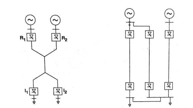
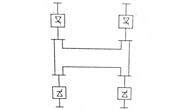
An MTDC system has several advantages over the alternative of point-to-point systems. For example, consider a system of two generating stations and two loads as shown in Fig. This is a radial system with two rectifiers and two inverters. To ensure the same level of flexibility in energy exchange, three two-terminal DC links will be required in addition to a link connecting the two receiving systems, which could be AC or DC. This would result in extra costs for the converter stations, and lines and additional power losses in an increased number of conversions.
The elimination of the AC collector system at the remote hydro generating stations can result in better efficiency in the operation of hydraulic turbines which are free to run at speeds independent of the system frequency.
- Asynchronous interconnection between adjacent power systems. When more than two systems are involved, an MTDC system for interconnection is more flexible and economical than employing several two-terminal DC links.
- Reinforcing an AC network that is heavily loaded. Consider an urban power system that is fed by a distant power station. It would be advantageous to arrange the power injection at more than one point so that the underlying AC network is not overloaded. This is easily achieved using an MTDC system with one rectifier station and several inverter stations.
Types of MTDC Systems
There are two possible types of MTDC systems
- (1) Series
- (2) Parallel
The parallel MTDC systems can be further subdivided into the following categories:
- (a) Radial
- (b) Mesh
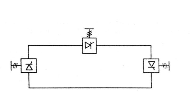
1. Series MTDC System
This is a natural extension of the two terminal system which is a series connected system. A three-terminal MTDC system is shown in Fig. This shows a monopolar arrangement, however, a homopolar arrangement with two conductors is also possible. The system is grounded at only one point which may be conveniently chosen. If the line insulation is adequate, the grounding point can be shifted, based on changes in the operating conditions. Grounding capacitors may also be used to improve insulation coordination and system performance during transients.
In a series-connected system, the current is set by one converter station and is common for all the stations. The remaining stations operate at a constant angle (extinction or delay) or voltage control. To minimize the reactive power requirements and the losses in valve damper circuits, the normal operating values of firing angles may be adjusted using tap changer control. At all times, the sum of the voltages across the rectifier stations must be larger than the sum of the voltages across the inverter station. In case of a drop in the voltage at the current-controlling rectifier station, the inverter with the larger current reference takes over the current control.
The switching in or out of a bridge is accomplished by deblocking/blocking and bypassing like that in a two-terminal system. The clearing of a fault in the DC line is also similar. The power réversal at a station is also done as in a two-terminal system, by reversing the DC voltage by converter control.
The power control in a two-terminal system is accomplished by adjusting the current while trying to maintain a constant voltage in the system. This is done to minimize the losses. However, in an MTDC series system, central control would be required to adjust the current in response to changing loading conditions. The local control of power would imply adjusting the voltage at the converter station using angle and tap controls. Using only one bridge or a 12 pulse unit for the voltage control and operating the remaining bridges at minimum (or maximum) delay angle can reduce the réactive power requirements.
2. Parallel MTDC System
Here, the operating philosophy of constant voltage AC systems is extended to DC systems. The currents in all the converter stations except one are adjusted according to the power requirement. One of the terminals operates as a voltage-setting terminal at a constant angle or voltage. An example of a 3-terminal radial system is shown in Fig. This shows a monopolar system but a bipolar arrangement would be normally used.
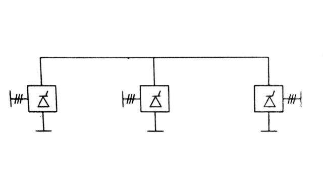
A radial system is one in which the disconnection of one segment of transmission would result in an interruption of power from one or more converter stations. In a mesh system, the removal of one link would not result in a disruption, provided the remaining links are capable of carrying the required power (with increased losses). A mesh system can be more reliable than a radial system. An example of a 4 terminal mesh system is shown in Fig.
The power reversal in a parallel MTDC system would involve mechanical switching as the voltage cannot be reversed. Also, the loss of a bridge in one converter station would require either the disconnection of a bridge in all the stations or the disconnection of the affected station.
Comparison of Series and Parallel MTDC Systems
The advantages and disadvantages of series and parallel MTDC systems are given below.
- High-speed reversal of power is possible in series systems without mechanical switching. This is not possible in parallel systems.
- The valve voltage rating in a series system is related to the power rating, while the current rating in a parallel connected system is related to power) This would imply that for small power ratings of the tap, the series connection may be cheaper even though valves have to be insulated for full voltage to ground. The parallel connection has the advantage of staged development in the converter stations by adding parallel converters as the power requirements increase.
- There are increased losses in the line and valves in series systems, in comparison to parallel systems. The system operation in series systems can be optimized by operating the largest inverter at rated voltage.
- Insulation coordination is a problem in series systems as the voltage along the line varies.
- The permanent fault in a line section would lead to a complete shutdown in a series-connected system, while it would lead to only the shutdown of a converter station connected to the line section in a radial MTDC system. With provisions for fast identification and clearing of faults in mesh-connected systems, there is no disruption of power transfer.
- The reduction in AC voltages and commutation failures in an inverter can lead to the overloading of converters as current is transferred from other terminals in a parallel system. The problem is severe if the rating of the inverter is relatively small. Increased values of smoothing reactors and voltage-dependent current limits can reduce the severity. However, the valve ratings would increase, resulting in increased unit costs. A recent study shows that the cost of 500 MW DC equipment (at 500 kV) would be 74% of the cost of a 1000 MW DC equipment. It is concluded that a practical limit to unequal inverter ratings may be 75%:25%、
- The control and protection philosophy in a series MTDC system is a natural extension of that in a two-terminal system. However, extension to parallel systems is not straightforward. Increased communication requirements and problems in recovery from commutation failures are associated with parallel systems. HVDC breakers of appropriate rating may be required for clearing faults in the DC line or converter stations.
From the relative merits and demerits of series and parallel MTDC systems described above, it may be concluded that a series connection is appropriate for taps of rating less than 20% of the major inverter terminal. Parallel connection is more versatile and is expected to be widely used in AC systems. The first application of a MTDC system is the Sardinia-Corsica-Italy link where an existing link between Sardinia and Italy is tapped at Corsica. This is a 50 MW parallel connected tap with two 100 kV six pulse thyristor bridges connected in series. A series tap was rejected for two reasons (i) the operating current due to frequency control can be as low as 10% of the rated current. This increases the voltage rating of the series tap. (ii) A series tap in inverter operation reduces the voltage at the main inverter terminal, requiring increased extinction angles. This is harmful to mercury arc valves as the probability of arc-through increases,
Commutation failure at Corsica can result in overcurrents of 7 p.u. Smoothing reactors of 2.5H are chosen to limit the overcurrents due to disturbances in the AC system.
Quebec-New England link from Radisson in Quebec to Sandy Pond in Massachusetts with a converter at Nicolet became operational in 1992 with two inverters and one rectifier of capacity 2250 MW. While it was planned to integrate an existing two-terminal HVDC link (from Des Canton to Comerford) with this system to form a 5 terminal MTDC system, this plan was dropped. Other plans to introduce the MTDC system were also shelved. The setback to planning for MTDC was primarily due to inadequate preparation in the development of control and protection concepts required for reliable system operation.
Frequently Asked Questions (FAQs)
-
What are the applications of the MTDC system?
Multi-terminal DC (MTDC) systems find applications in renewable energy integration, long-distance power transmission, grid interconnections, and enhancing grid stability through flexible power flow control and fault management.
-
What is the MTDC?
MTDC stands for Multi-Terminal Direct Current. It’s a power transmission system where multiple DC terminals are interconnected, allowing for efficient long-distance power transmission, renewable energy integration, and grid stabilization.
-
What equipment is excluded from MTDC?
Equipment excluded from MTDC systems typically includes traditional AC-based components such as transformers and synchronous generators. MTDC systems primarily consist of converters, DC lines, and associated control and protection systems.
Read Also:
- DC Filters | Criteria, Carrier Frequency, and RI Noise
- DC Breakers | Characteristics, Types, and Applications
- Comparators | Definition, Types of Comparators
- Potential Transformer | Construction, Working, and Errors
- Instrument Transformer | Introduction, Types, and Need


Leave a Reply