
Table of Contents
Design of a Single-Tuned Filter
The single-tuned filters are designed to filter out (usually) characteristic harmonies of a single frequency. The equivalent circuit seen by the harmonic current Ih generated by the converter is shown in Fig. ZFh and ZSh are the filter and system impedances at the harmonies frequency (hf).
The harmonic current in the filter is given by
IFh = Ih |ZSh | / |ZSh + ZFh|
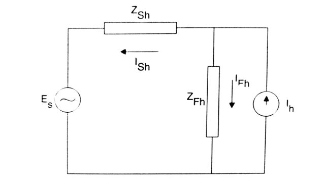
The harmonic voltage at the converter bus is
Vh = IFh |ZFh| = Ih / |YFh + YSh| = Ih / |Yh|
The basic objective in designing the filter is to select the filter admittance YFh to minimize Vh or satisfy the constraints on Vh The problem of designing a filter is complicated by the uncertainty about the network admittance (YSh) There are two possible representations of system impedance in the complex plane. These are (a) the impedance angle is limited (see Fig.(a) and (b) the impedance is limited both in angle and impedance. The impedance is assumed to lie in the region shown in Fig. (b) in which R1, R2, and θm obtained from the system characteristics.
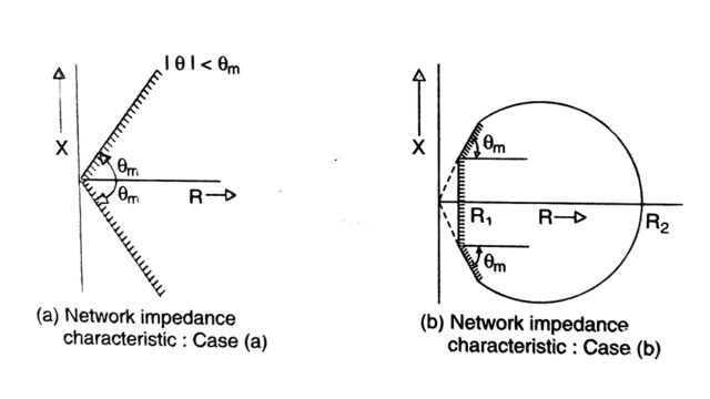
It is to be noted that (a) or (b) reflect the broad assumptions about the nature of system impedance. The assumption (b) requires more knowledge of the system than (a). Having complete information on the network impedance characteristic will result in the economic design of filters and also a realistic assessment of the harmonic distortion of the converter bus voltage.
Although assumption (a) is rather simplistic, it allows a simplified computation of the optimum value of Q. In computing the optimum value of Q, we need to minimize the maximum value of Vh. Since we do not know the exact network impedance (except that its angle is limited), we assume the worst-case scenario for the network admittance that results in maximizing Vh. The optimum value of Q corresponds to the lowest value of the upper limit on Vh.
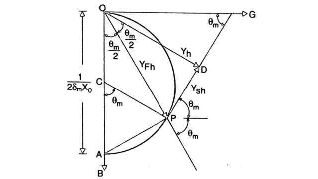
The value of Yh (the net admittance seen by the converter) is reduced if the detuning parameter 5 is maximum = δm. For a specified δm and X0, the locus of the filter impedance(as Q is varied) is a semicircle in the 4th quadrant of the G-B plane as shown in Fig. The diameter of the circle is 1 / (2δm X0). From the figure’s geometry, It can be seen that minimum Yh occurs when θ = θm. The optimum value of Q can be obtained from game-theoretic analysis. Suppose one selects YFH (OP) arbitrarily (the tip of YFH lying along the semicircle).
In that case, the network can select YSH such that the vector Yh (OD) is perpendicular to PD (the vector YSH) and ensure Yh is a minimum. To maximize the minimum magnitude of Yh, it is necessary to have PD tangential to the circle at point P. Thus, we select YFH to maximize Yh when the network (viewed as an adversary, not under our control) tries to minimize it.
To compute optimum Q, we note that triangle OPC is isosceles with angle COP = angle CPO = θm/2. The angle of the impedance ZFh is (90 – θm / 2) and we have,
tan(90 – θm / 2 ) = Qopt × (2δm) = cot(θm /2)
Hence,
Qopt = cot(θm /2) / 2δm= 1+cosθm / 2δmsinθm
Since |Yh| = YFh cos(θm/2), |YFh | = cos(θm/2)/(2δmX0), we can derive the expression for Vh using Eq. We finally get,
Vh = Ih / |YFh +YSh| = 4 δm X0Ih / 1+cosδm
Minimum cost tuned filters
The costs of the reactor and the capacitor which make up the tuned filter are dependent on their respective ratings. The rating of the capacitor is given by
SC = I2F1XC1 + I2FhX0
where IF1 is the fundamental frequency current in the tuned filter given by
IF1 = V1 . (XC1 – XL1) = V1 / X0 (h – 1/h) = (hV1 / (h2 – 1) . X0
In deriving the above equation, the effect of the resistance, R is neglected. V1 is the fundamental frequency component of the voltage at the filter bus. (Actually, the harmonic components in the bus voltage in steady state, are neglected as filtering of harmonics in the source current supplied to the converter is assumed to be effective). XC1 = X0h is the reactance of the capacitor and XL1 = X0h is the reactance of the inductor at the fundamental frequency.
The rating of the reactor (SL) is given by SL = I2F1XL1 + I2FhX0
The size of the filter (S) is defined as the reactive power supplied by the capacitor (at the fundamental frequency). Thus, we get
SC = S + I2FhX0
SL = S / h2 + I2FhX0
The total cost of the filter (K) is given by
K = SCUC + SLUL
where UC and UL, are the unit costs of the capacitor and inductor, respectively. Substituting Eqs. we get an expression for the total cost as a function of the size of the filter. Since our objective is to determine the optimum size of the filter that will minimize the total cost, we need to express X0 in terms of the size S. It can be easily shown that
X0 = N / S, N = V21h3 / (h2 – 1)2
Substituting Eqns. , we get,
K = AS + BS-1
where A = UC + UL, B = I2Fh N(UC +UL)
It is to be noted that IFh is expressed in terms of Ih (the harmonic current injected by the converter)
Since A and B are constants, the cost of the filter is minimum when the size of the filter is minimum given by
Sopt = (B/A)1/2
The filtering would improve with the increased size of the filter. Hence the choice of the filter size will not be below that given by the above expression.
Design of a High Pass Filter
This is a second-order (damped) filter described earlier. For harmonic frequencies equal to or higher than 17, a second-order high-pass filter is usually provided. By defining the following parameters,
h0ω=1/√ LC, X0 = √ L/C, Q = R/X0
the following values can be chosen
0.5 < Q < 2
h0 ≤√2hmin
where hmin min is the smallest value of h to be handled by the filter. The choice of h0 given above implies that the filter impedance at the hmin has decreased approximately to the value of R. The filter impedance is given by Eqn. The reactive power supplied by the filter QF is
QF = (h0 / (ho2 – 1))(V12 / X0)
In deriving the above, the voltage across the inductor at the fundamental frequency is neglected. It can be shown that the filtering is improved if QF, is increased and a higher value of h0 can be chosen. Hence, it is advantageous to design a high pass filter to exclude six pulse operations. There is no optimum quality factor, Q in the case of high-pass filters. Q is chosen for providing the best performance of the filter over a band of frequencies higher than those covered by tuned filters. The performance of these filters is insensitive to deviations in the frequency or filter parameters.
Double and Triple Tuned Filters
A single-tuned filter can be used to filter one characteristic harmonic (or a non-characteristic harmonic when required). Multiple single-tuned filters are required to filter several (discrete) harmonics. For example, at least two single-tuned filters are required for twelve pulse converters (to filter 11th and 13th d harmonics). Since AC filters also provide the required reactive power which is a function of the power flow in the HVDC link, there is a need to arrange the filters into switchable sections (filter banks) which adds to the cost. An alternative is to provide switchable shunt reactors that are switched in at low DC power levels.
This also is a costly option with increased space requirements. Weak AC systems (with low SCR) also impose an upper limit on the size of the filter bank to limit the voltage fluctuations (flicker) caused by the switching of a filter bank. Thus, coordination of the filtering and supplying reactive power considerations dictate the adoption of double and triple-tuned filters. The advantages also include (i) only one inductor (L1) is subject to full line impulse voltage and (ii) power loss at the fundamental frequency is considerably reduced.

Electrically, neglecting losses, a double-tuned filter is identical to two single-tuned filter branches shown in Fig. (b). Similarly, a lossless triple-tuned filter is identical to three single-tuned filter branches.
The double and triple-tuned filters shown in Figs have a single resister R each. Additional damping resistors can be applied in parallel with reactor L, and/or Ly and L to produce a damped characteristic.
Analysis of a Double-Tuned Filter
The impedance of the filter shown in Fig. (a) (neglecting the effect of R1) as a function of the complex frequency (s) is given by
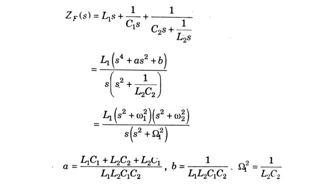
where
The zeros of ZF(s) lie on the imaginary axis corresponding to the two frequenciesω1 and ω2. The poles are also on an imaginary axis corresponding to ω = 0 and ω = Ω. From the properties of the impedance of one-port L-C networks, we can state
0 < ω1 < Ω1 < ω2
Since the double-tuned filter is equivalent to the two single-tuned filters shown in Fig.(a), we can compare the impedances of the two circuits and obtain the following results
L1 = LaLb / (La + Lb), L2 = La + Lb, C1 = Ca + Cb, C2 = CaCb / (Ca + Cb)
From the above, it follows that
L1L2 = LaLb, C1C2 = CaCb
The impedance of the double-tuned filter as a function of the frequency is obtained by substituting s = jωh in the expression given in Eq. Note that ω is the fundamental (system) frequency and & is viewed as a continuous variable.
Defining ωr = 1 / √ L1C1 , X1 = ω1L1 = 1 / ω1C1 , hr = ωr / ω, H1 = Ω 1 / ω, X2 = L2 = 1 / Ω 1C2
We can express the impedance as a function of h as
ZF (jωh)= jX1 = (h / hr – hr / h) + X2 / j(h / H1 – H1 / h)
J[X1 . (h2 – h2r ) / (hhr) – (X2H1h) / (h2 – H12]
To compute ω1, and ω2 we equate the RHS of Eq to zero and get the following quadratic equation in h2 given below
h4 – (hr2 + H12 + X2 / X1 . H1hr). h2 + hr2H12 = 0
The reactive power (QF) supplied by the filter is given by
QF = V12 / ZF1
where ZF1 = (hr2 – 1) . X1 / hr – (X2H1) / (H12 – 1)
Analysis of Triple-Tuned Filters
The impedance of a lossless triple-tuned filter as a function of complex frequency s is given by
ZF(s) = L1(s2 + ω12)(s2 + ω22)(s2 + ω32) / (s(s2 + Ω12)(s2 + Ω22))
where ω1, ω2 and ω3 are frequencies which have to be filtered Ω1 and Ω2 are defined by
Ω1 = 1 / √L2C2 , Ω2 = 1 / √L2C3
The impedances of the filter as a function of ho (h is treated as a continuous variable) are given by
ZF (jhω) = jX1 (h / hr – hr / h) + X2 / j (h / H2 – H1 / h + X3 / j(h / H2 – H2 / h
where
H1 = Ω1 /ω, H_{2} = Ω2 /ω, hr = ωr / ω, ωr = 1 / √L1C1
X1 = ω1L1 = 1 / ω1C1, X2 = Ω1L2 = 1 / Ω1C2, X3 = Ω2L3 = 1 / Ω2C3
To compute ω1, ω2, and (the zeroes ZF) we equate the RHS of Eq. to zero. We finally get a cubic equation in h2 given by
h6 – a1h4 + a2h2 – a3 = 0
a1 = hr2 + H12 + H22 + hr (X2 /X1 . H1 + X3 / X1. H1)
a2 = H12H22 + hr2 (H12 + H22) + hrH1H2 . (X2 /X1 . H2 + X3 / X1 . H1)
a3 = H12H22hr2
h1 = ω1 / ω, h2 = ω2 / ω, h3 = ω3 / ω are the three real roots of Eq. It is easily observed that the product of the real roots is √a3. This implies that
ω1ω2ω3 = ωr
we have to select Ω1 and Ω2 such that
0 < ω1 < Ω1 < ω2 < Ω2 < ω2
Frequently Asked Questions (FAQs)
-
What do you mean by filter?
A filter is a device or mechanism used to remove or separate particles or substances from a mixture, often employed in various contexts like air purification, water treatment, or data processing.
-
What is a filter used for?
A filter is utilized to remove impurities, particles, or unwanted elements from a substance or data set, ensuring purification, refinement, or selective extraction for improved quality or relevance.
-
What is the advantage of a filter?
Filters offer numerous advantages, such as enhancing the quality of substances like air or water by removing pollutants, facilitating targeted information retrieval from large datasets, and improving efficiency by focusing on relevant elements while discarding unnecessary or undesirable ones.
Read Also:
- Harmonics | Introduction, Generation, and Non – Characteristics
- DC Filters | Criteria, Carrier Frequency, and RI Noise
- Reactive Power Control | Requirement, Sources, and Transients
- DC Breakers | Characteristics, Types, and Applications
- Smoothing Reactor and DC Line | Transient overvoltages, Protection, and Effects


Leave a Reply