Table of Contents
Introduction of DIAC
DIAC simply stated as “Direct for alternating current“. A DIAC is a three layer, two electrode full wave or bidirectional diode that can be switched from OFF state to ON state for either polarity of applied voltage. DIACS are almost never used alone, but in conjunction with other thyristor devices. In phase control circuits, DIACS are utilized as triggers to deliver gate pulses to a TRIAC or SCR. They are silicon devices that are voltage-triggered and bidirectional. To reduce the DC component in the load circuit, DIAC voltage options between 27 V and 70 V offer trigger pulses that are closely matched in symmetry at the positive and negative break-over points.
Symbol of DIAC
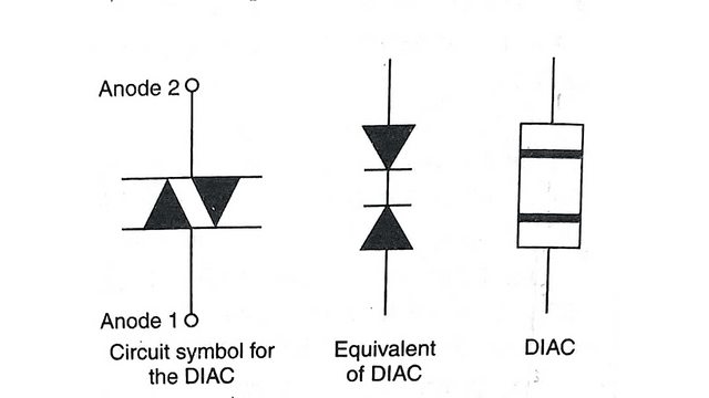
A combination of two diodes connected in parallel but in the opposing directions creates the DIAC symbol. The terminals for DIACS cannot be identified as anode and cathode as they are for a diode since they are bi-direction devices. Instead, they might be identified as A1 and A2, or MT1 and MT2, the “Main Terminal.”
In accordance with the polarity of the applied voltage, each terminal can act as either an anode or a cathode. Which end junction is active and which one is bypassed is also determined by the applied polarity. Asymmetric DIACS are available despite the fact that most DIACS have symmetric switching voltages. Power dissipations for typical DIACS range from half a watt to one watt.
Construction of DIAC
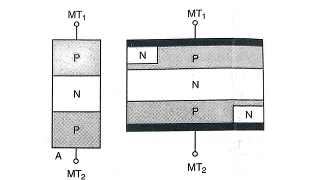
Either a three-layer or a five-layer manufacturing method is available for the DIAC. Both three-layer and five-layer architectures share the same VI characteristics, however their “switching on” methods differ. Switching happens in the three-layer structure when the reverse biased junction goes through reverse breakdown.
The DIAC is constructed in much the same way as a bipolar transistor. The device has three alternately doped semiconductor layers as shown in figure. However, it differs from the BJT because the doping concentrations around both junctions are equal and leads are attached only to the outer layers. No electrical connections are made its middle region.
Since the DIAC has only two leads, it is often packaged metal or plastic case which has axial leads. Therefore, the device often resembles ordinary PN Junction diode in appearance. However, device is sometimes packaged a conventional BJT but with only two leads.
Operation of DIAC
Since both of its junctions are equally doped, the DIAC has the same affect on currents flowing either direction through leads. In either direction, one junction will always be forward-biased while the other reverse-biased. In each case reverse-biased junction primarily controls current flowing through DIAC and the device operates as if it contains two PN junction diodes that are but are connected back-to-back.
DIAC circuits use the fact that a DIAC only conducts current only after a certain breakdown voltage been exceeded. The DIAC remains in an OFF state (conducts only leakage current) in either direction until applied voltage in either direction high enough to cause respective reverse-biased junction to break down. The actual breakdown voltage will depend upon specification for the particular component type.
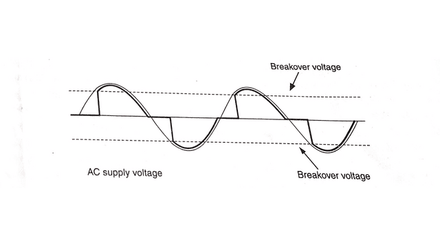
When this occurs, the components’ combined resistance quickly drops, which in turn causes a sharp decline in the voltage drop across the DIAC and a corresponding increase in current, turning on the device. Practically speaking, the increase in current is caused by a small resistance in series with the gadget. When the current flowing through the DIAC falls below a specific amount known as the holding current, it will still be in a conducting condition. When the holding current is reached, the DIAC changes back to its high resistance, or non-conducting, state.
VI Characteristics of DIAC
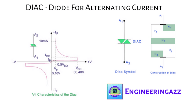
The DIAC exhibits a high impedance blocking state up to voltage break-over point (VBO) above which it enters negative-resistance region. The voltage-current (V-I) characteristic curve for a typical DIAC is shown in figure. This curve shows the relationship between the current flowing through the device in either direction (+1A and -1A) and the corresponding voltage across the device in each direction (+V and -V).
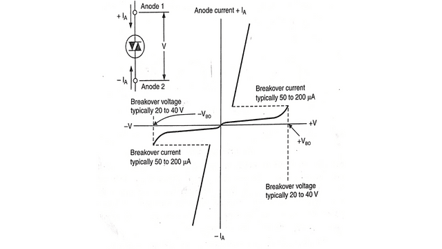
As seen in Figure, the current through the DIAC stays low until the voltage across the device rises to the point at which it fails in either direction. These voltages, known as the DIAC’s break-over voltages and denoted as +VBO and -VBO as indicated in the figure, are needed for the DIAC to breakdown. A common device will typically have +VBO and -VBO values between 28 and 36 volts.
Observe how the current through the DIAC grows quickly while the voltage across the device falls after the +VBO and -VBO levels are reached. In other words when break-over occurs, the resistance of the DIAC decreases rapidly as current increases and the net result is a decrease in voltage across the device. Therefore, once the break-over point is reached the DIAC exhibits a negative resistance characteristic.
Frequently Asked Questions (FAQs)
-
What is full form of DIAC?
The full form of DIAC is Diode For Alternating Current. A DIAC is a three layer, two electrode full wave or bidirectional diode that can be switched from OFF state to ON state for either polarity of applied voltage.
-
What are the drawbacks of DIAC?
The drawback of the DIAC is the same as it was for the four-layer diode: it cannot be triggered at just any point in the ac power cycle; it triggers at its preset break-over voltage only.
-
What are characteristics of DIAC?
The main characteristics of DIAC are:-
* Breakover Voltage
* Voltage Symmetry
* Breakover current
* Power Dissipation -
Where the DIAC are used?
The DIAC is widely used in electronic components. The main use of DIAC is in conjunction with TRIACs to equalise their switching characteristics. The DIACs are widely used in AC applications. Some applications include gate triggers for light controls, dimmers, and power pulse circuits.


Leave a Reply