Table of Contents
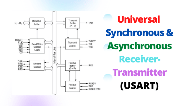
Universal Synchronous and Asynchronous Receiver-Transmitter (USART)
A universal synchronous & asynchronous receiver-transmitter (USART) is a part of peripheral communications hardware that allows a computer to communicate with serially connected devices both synchronously and asynchronously.
A USART is a device that allows serial data communication from a serial port using the RS 232 protocol.
A serial communications interface is also known as a USART (SCI).
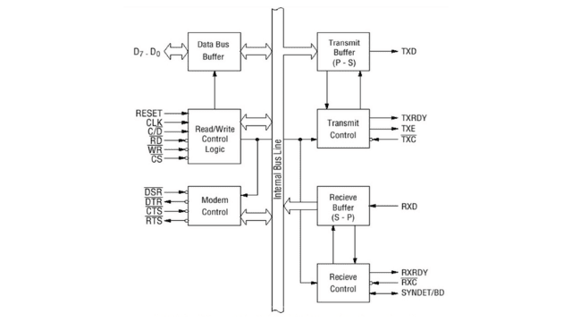
In the above diagram, we explain the following part of USART
- D0-D7 :- This is an 8-bit data bus used to read or write status, CMD (Command) word or data from or to the 8251.
- R͞D :- This low active input to the 8251 informs it that the CPU is reading data or status information from its internal registers.
- W͞R :- This active low input to the 8251 informs it that the CPU is writing data or control words to it.
- C͞S :- The 8251 has an active low chip select input. If it is set to high, no read or write operations on 8251 can be performed. If this pin is high, the data bus is tristated.
- RESET :- A high on this input forces the 8251 into an idle state. For proper reset operation, the minimum required reset pulse width is 6 clock states.
- C/D̅ (Control Word/Data) :- When input is high, it controls or status registers at the address. When it is low, the data buffer is addressed.
- CLK :- The input is normally connected to the clock generator output and is used to generate internal device timings. The input frequency should be at least 30 times higher than the data bit transfer rate of the receiver or transmitter.
- DSR :- This input can be used as a one-bit inverting input port for general use. The CPU can check its status using a status read operation. When communicating with a modem, this is generally used to check if the data set is ready.
- DTR :- This out may be used as a general purpose one bit inverting output port. This can be programmed low using the command (CMD) word. This is used to indicate that the device is ready to accept data when the 8251 is communicating with a modem.
- CTS :- CTS stands for Clear to Send. When its value is low, which means zero, then this pin is working.
- RTS :- RTS stands for Request to Send. This output can also be used as a general-purpose one-bit inverting output port that can be set to low to tell the modem that the receiver is ready to receive a data byte. This signal is used to send and receive data from a modem. This signal is used to communicate with a modem.
- TXD (Transmitted Data Output) :-This is the output pin which carries the serial stream of the transmitted data bits. It also carries other information like the stop bit, start bit, and parity bit.
- TXRDY (Transmitter Ready) :- This output signal indicates that the internal terminal circuit of the transmitter is ready to accept the new signal for transmission from the CPU. The TXRDY status bit will indicate the empty or full status of the transmitter data input resistor, which is held in polled operation.
- TXE (Transmitter Empty) :- The transmitting data becomes empty, so the TXC output goes high and becomes low when the data is received from the CPU.
- TXC (Transmitter Clock Input) :- This is active low pin. This pin is used to control the rate of signal to be transmitted. The baud rate is equal to the TXC frequency in synchronous mode but in asynchronous mode the baud rate is 1, 1/16, 1/64 of the TXC.
- RXD (Receive Data Input) :- This input pin of 8251 receives a composite stream of the data to be received by 8251.
- RXRDY (Receiver Ready Output) :- This output indicates that the 8251 contains a character to be read by the CPU. The RXRDY signal may be used either to interrupt the CPU or may be polled by the CPU.
- RXC (Receiver Clock Input) :- This receiver clock input pin controls the rate at which the character is to be received.
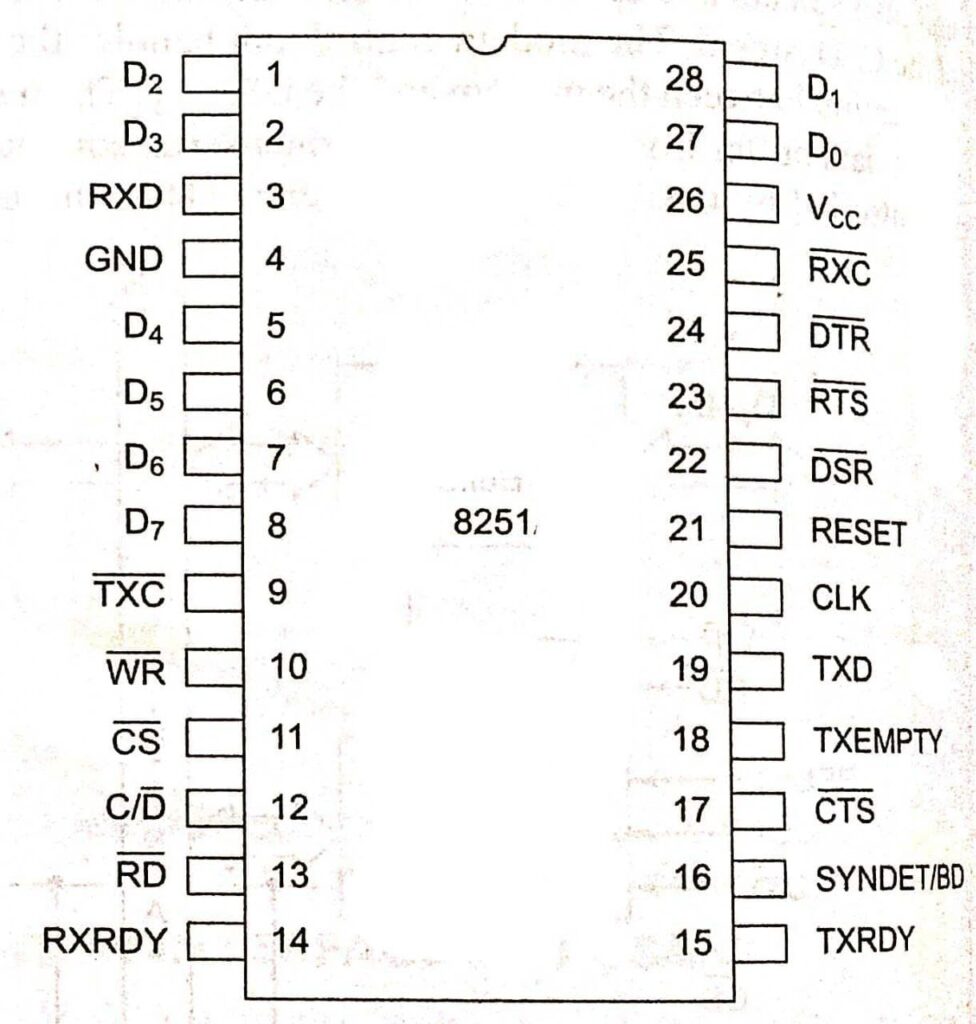
USART Pin Diagram (8251)


Leave a Reply