Table of Contents
DC Generator
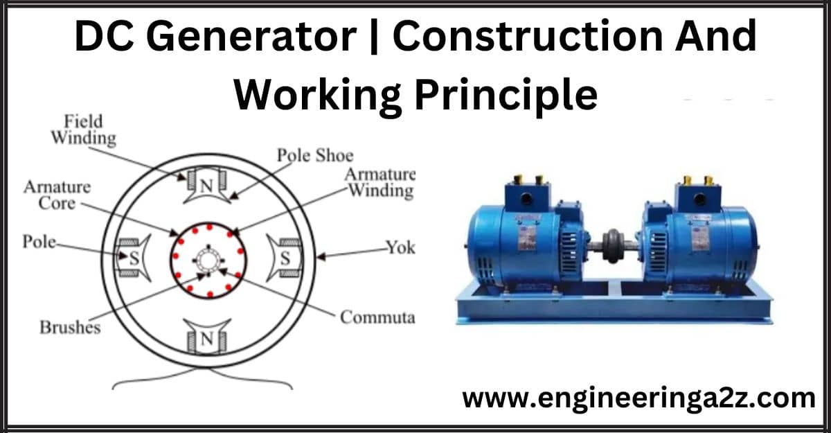
A DC generator is an electrical machine whose main function is to convert mechanical energy into electricity. When the conductor slashes magnetic flux, an emf will be generated based on the electromagnetic induction principle of Faraday’s Laws. This electromotive force can cause a flow of current when the conductor circuit is closed.
Principle of D.C. Generator
The working principle of a d.c. the generator is electromagnetic induction i.e., whenever flux is cut by a conductor, an e.m.f. is induced which will cause a current to flow if the conductor circuit is closed. Thus, the essential parts of an electrical generator are:
- A magnetic field,
- Conductor or Conductors.
- The motion of the conductor relative to the field.
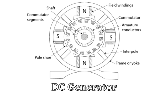
Construction Of D.C. Generator
The construction of a d.c. machine (Generator or Motor) is basically the same. In fact, the same machine may be run as a generator or motor.
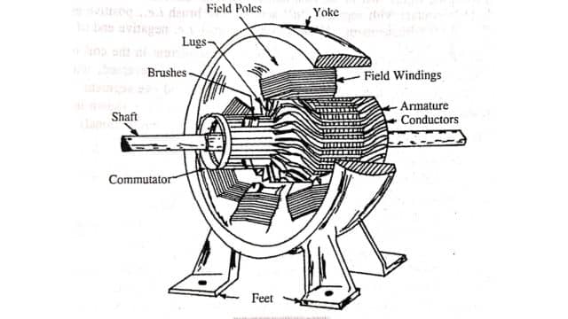
(1) Field Magnet Frame or Yoke: The yoke or outer frame is the covering provided to a d.c. generator and it serves the following purposes.
- It provides mechanical support for the poles.
- It acts as a protective cover against mechanical damage.
- It provides a passage for the magnetic flux produced by the poles.
For small generators, yokes are made of cast iron. These are heavy but the cost is low. For larger machines, usually cast steel or rolled steel is used, because this material is more permeable than cast iron. It is economical because for a given magnetic conductivity its weight is only 40% as much as of cast iron.
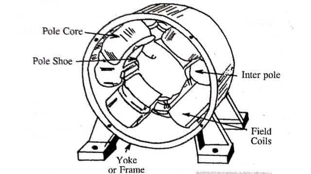
(2) Pole Cores and Pole Shoes: The pole core itself may be made of a solid piece of cast iron or cast- steel, but the pole shoe is laminated and is screwed to the pole face by means of counter-sunk screws. The pole cores may be made of thin laminations of steel, rivetted together. This type of pole is held in position with the frame by means of bolts. The pole shoe serves two purposes as under.
- It supports the pole coils.
- Being of a larger cross-section, it spreads the flux and also reduces the reluctance of the magnetic path.
(3) Pole Coils or Field Coils: The pole coils or field coils consist of copper wire and are former wounds. After removing the former, the coil is placed in position around the pole core. When current is passed through these coils, they electro-magnetize the poles which produce the necessary flux which is cut by the armature conductors when in motion.
(4) Armature Core: The armature core is cylindrical in shape. It is a rotating part of the machine. Its body is made up of soft iron stampings or laminations to reduce the eddy current losses. The laminations are keyed to the shaft. These are insulated from each other by varnish. At the outer periphery, slots are cut as shown in Fig. DCG- The armature conductors (winding) are placed in these slots.
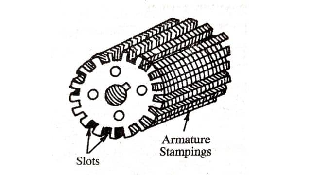
The armature core serves the following purposes.
- It provides a path of low reluctance to the magnetic flux.
- It houses the armature conductors.
The use of high-grade Silicon steel is made to reduce the hysteresis loss, which is due to the reversal of flux caused by the rotation of the core in the magnetic field.
(5) Armature Winding: The armature coils are usually former wounds. The conductors are placed in the armature slots which are lined with tough insulating material. The slot insulation is folded over the armature conductors placed in the slots and is secured firmly by bamboo or fiber wedges.
The armature windings are usually conductors covered with a single cotton cover, double cotton cover, or enameled wire. On the basis of connections, these are of two types:
(1) Lap winding
(ii) Wave winding.
(6) Commutator: The commutator is cylindrical in structure and is built up of wedge-shaped hard-drawn copper segments. The segments are insulated from each other by a thin sheet of high-quality mica. To prevent them from flying out under the action of centrifugal forces, the segments are provided with V-grooves, which are insulated by a conical mica-nite ring. The function of the commutator is to facilitate the collection of current from the armature and to rectify the A.C. induced in the armature into D.C.
(7) Brushes: The function of brushes is to collect current from the commutator and supply it to the external load circuit. These are usually made of carbon and are rectangular in shape. These brushes are housed in brush holders. These are held in position under spring tension, the pressure of the spring can be adjusted by altering the position of the lever in the notches. Copper brushes are only used for machines delivering large currents at low voltages.
(8) Brush Holders: The function of the brush holder is to hold the brushes.
There are many types of brush holders but the box type probably is the best. The box-type holder is mounted on a spindle that passes through the hole. The brush can slide into the rectangular box open at both ends. It is pressed on the commutator by a spring whose tension can be adjusted by placing the small lever in one of the notches shown. A flexible copper lead at the top of the brush conveys the current from the commutator to the outer circuit in the case of generators.
(9) Bearings: These are supported in end covers, because of reliability, ball bearings are usually employed. Though for heavy-duty, roller bearings are employed. These are used to reduce friction and have less wear and tear.
(10) Shaft: The material of the shaft is mild steel. It is used to transfer mechanical power from or to the machine. The rotating parts e.g., Armature, commutator, etc. are mounted to the shaft.
Working Of D.C. Generator
According to Faraday’s law of electromagnetic induction, we know that when a current-carrying conductor is placed in a varying magnetic field, an emf is induced in the conductor. According to Fleming’s right-hand rule, the direction of the induced current changes whenever the direction of motion of the conductor changes. Let us consider an armature rotating clockwise and a conductor at the left moving upwards.
When the armature completes a half rotation, the direction of the motion of the conductor will be reversed downward. Hence, the direction of the current in every armature will be alternating. But with a split ring commutator, connections of the armature conductors get reversed when a current reversal occurs. Therefore, we get a unidirectional current at the terminals.
Frequently Asked Questions (FAQs)
-
What are the types of generators?
Types of generators are:
(a) AC generators
(b) DC generators -
Define yoke.
The external structure of the DC generator is known as Yoke.
-
What are the types of self-excited generators?
Types of self-excited generators are:
(a) Series generator
(b) Shunt generator
(c) Compound generator
Read Also:
- Advantages | Disadvantages and Applications of Electric Power
- Relay | Construction and Working
- Heat Engine | Internal Combustion Engine
- Megger | Construction & Working | Engineeringa2z
- Three Phase Transformer | Construction & Working


Leave a Reply