Table of Contents
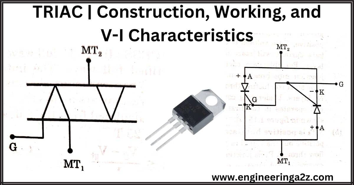
TRIAC
An SCR can be conducted in only one direction. So only the positive half cycle of the circuit can be controlled. But the requirement of many applications is to control both inputs of the half cycle. This requirement is fulfilled if we connect the two SCRs in an anti-parallel combination. This arrangement is known as the TRIAC. Therefore, a triac can conduct in both directions, So it is called a bidirectional device. The term TRIAC is obtained from the capital letters of TRlode and AC.
Read Also
DIAC | Construction | Working and V-I Characteristics
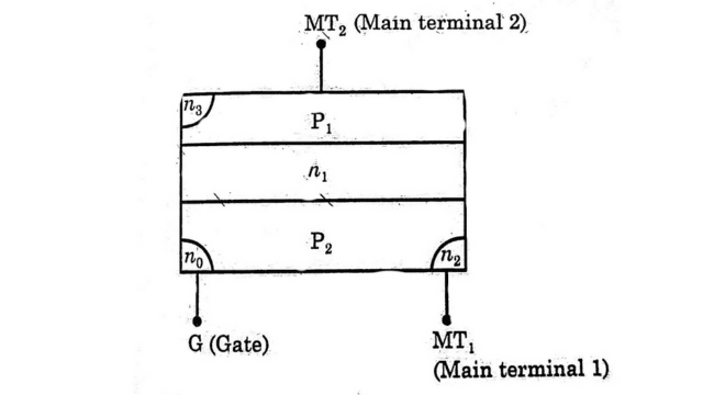
Construction of TRIAC
The figure shows the constructional arrangement of TRIAC. As the triac can conduct in both directions, therefore the terms anode and cathode are not applicable to triac. It consists of three terminals MT1, MT2 and Gate G. When the two PNPN SCR are connected in antiparallel configuration with a common gate, then TRIAC can be found.
Working Principle of TRIAC
Triac is a bidirectional device. When no signal to the gate, the trine will block both half cycles of ac applied voltage. The Triac can be turned on in each half cycle of the applied voltage, when MT2, is +ve w.r.t MT1: or when MT1: is +ve w.r.t MT2: with a positive or negative gate signal applied.
TRIGGERING PROCESS: There are four turn-on processes of a triac that can be explained as under,
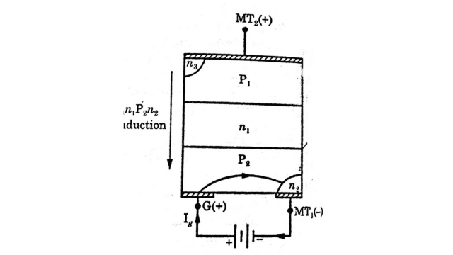
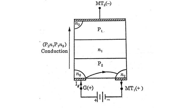
(a) MT2 is positive and Gate G is also positive w.r.t. MT1 – When MT2 is positive w.r.t MT1, the junction P1 N1 P2 N2 are forward biased but the junction N1P2 is reverse biased as shown in figure. When the positive, Gate voltage is applied, the gate current will start flowing in the P2 N2 layer. For this gate current (Ig), the junction N1P2 breakdown. As a result, triac starts conducting through P1 N1 P2 N2 layers. Under this condition, triac will operate in the first quadrant as shown in Figure.
(b) MT2 is positive but Gate (G) is negative w.r.t MT1 – When MT2 is positive but the signal to gate terminal is negative, gate current will start flowing through Pa no junction as shown in the figure. In this condition reverse biased junction plane is forward-biased. As a result, triac starts conducting through P1 N1 P2 N0 layers.
Due to the potential of layer P2, à current will be established in the P2 layer from left to right as shown by dotted in the figure. Therefore a right-hand portion of triac P1 N1 P2 N2 starts conducting. In this triggering process, a large gate current will be required.
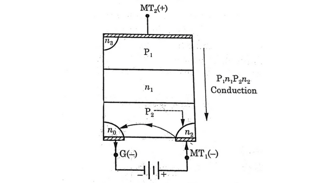
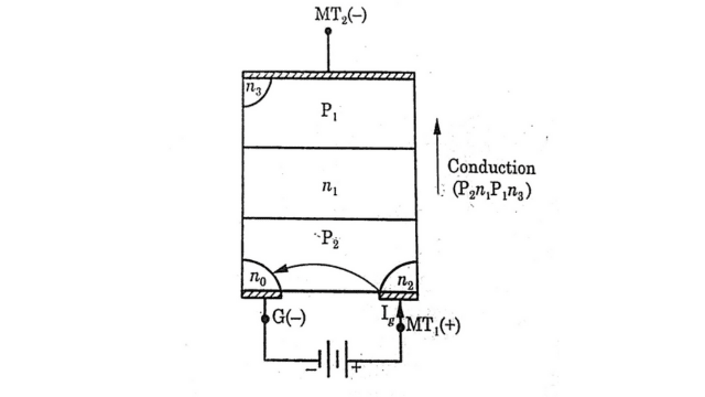
(c) MT2 is negative but Gate (G) is positive w.r.t. MT1 – When MT2 is negative w.r.t MT1, but the signal to the gate (G) is positive, then the junction N1 P1 is reverse biased. When the gate current starts to flow, the reverse biased junction N1 P1 breakdown. Finally, the layers P2 N1 P1 N3 start conducting as shown in Figure. Under this condition, the device operates in the third quadrant as shown in the V-I characteristics of triac.
(d) MT2 is negative and Gate (G) is also negative w.r.t MT1 – When the MT2 is negative w.r.t MT1, then gate current (Ig) starts to flow from the pa na region. Therefore the reverse biased junction N1 P1 is the breakdown. Finally, the layers P2 N1 P1 N3 start conducting as shown in Figure.
V-I Characteristics of TRIAC
The figure shows the V-I characteristics of TRIAC. the TRIAC can be conducted in two quadrants (quadrant 1 and quadrant 3) either a positive or negative gate voltage is applied.
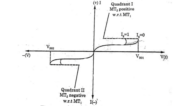
As with SCR, the triac remains in the off state until the breakdown voltage Vво1 and Vво2 is not reached. When the gate signal is zero, the breakdown voltages are Vво1 and Vво2. As the gate current is increased (I = 1), then the breakdown voltage will be reduced.
Applications of TRIAC
Triac applications are given below:
- It can be extensively used in residential lamp dimmers and heat control.
- It can also be used for speed control of small single-phase series and induction motors.
Frequently Asked Questions (FAQs)
-
What is TRIAC?
TRIAC is a bidirectional device that conducts in both directions. The symbol of TRIAC is shown below.
-
What is latching current?
It is the minimum forward current of an SCR which must be attained before the gate firing is removed at turn on for maintaining the conduction.
-
What is holding current?
It is the minimum forward current of an SCR which must pass through the device in order for it to remain in the “ON” state. The device is to be turned off when the forward anode current is below the holding current.
Related Posts
- Bipolar Junction Transistor (BJT): Types, Working, Construction, Advantages

- MOSFET | Working Principle | V-I Characteristics & Applications

- Full Wave Rectifier | Definition, Types and Working

- Cathode Ray Oscilloscope (CRO) Construction and Working Principle

- Solar Cell or Photovoltaic Cell Construction and Working

- B.Tech – Electrical Engineering Previous Year Question Papers Download


Leave a Reply