Table of Contents
Dual Converter
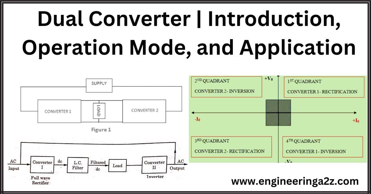
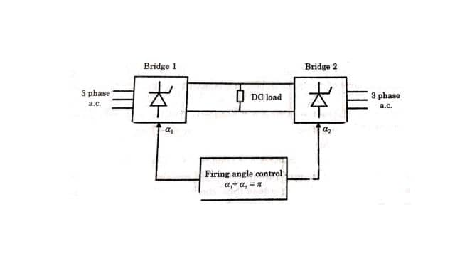
A dual converter is generally used to get reversible DC for a given load. If the four-quadrant operation is required without any mechanical changeover switch, two full converters can be connected back to the load circuit. Such an arrangement using two full converters in antiparallel connected to the same de-load is called Dual Converter. The basic block diagrams of the dual converter are shown in the figure.
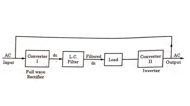
A dual converter has two converters or bridges. One bridge acts as a rectifier and the other bridge acts as an inverter.
Operation Mode of Dual Converter
There can be two modes of operation in the dual converter.
- Non-circulating current mode
- Circulating current mode
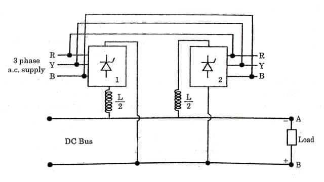
These two modes of operation are explained with the help of a schematic diagram fig. of a 3-phase dual converter as shown in Figure.
Non-Circulating Current Mode: In this mode, only one of the bridges is triggered. Fig. shows the polarity when Bridge 1st is triggered i.e. point A is negative and point B is positive. When reversal of output voltage is required, the firing pulses to the conducting bridge are stopped and the 2nd bridge is triggered. But as the conducting SCRs in the first bridge will take some finite turn-off time (i.e. when current through them becomes zero), a short dead time must be allowed before the second bridge is gated.
That is why a current sensor is used which ensures that all SCRs in the first bridge are turned off before the firing pulses are applied to the second bridge. If both the bridges are allowed to be turned on simultaneously, this causes a short circuit on the input which is avoided by using dead time. In a non-circulating current mode, both the bridges AC in rectifier mode only, and hence both can be half controlled only or fully controlled.
Circulating Current mode: In circulating current mode both the bridges are gated simultaneously in such a way that one operates in rectifying mode and the other in inverting mode to avoid short circuits. This mode requires fully controlled bridges only. Fig. shows the polarity (A negative, B positive) when the bridge is gated to work as a rectifier and bridge 2 is gated to work as an inverter. It will be good to recollect that any line commutated bridge converter with inductive load has an average output voltage equation.
V0 = K cos a
Where k is a constant and a is the firing angle.
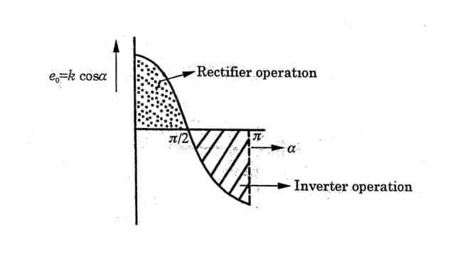
And also, when the value of a is less than x/2, the converter operates in rectifying mode, and when a > x/2, the same converter operators in inverting mode. This is shown in fig. after plotting the equation
In circulating current mode, the internal voltage of the rectifier is kept higher and that of the inverter is lower than the output voltage. For this to achieve, if the firing angle of bridge 1 (Acting as a rectifier) is taken to be at (where an
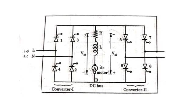
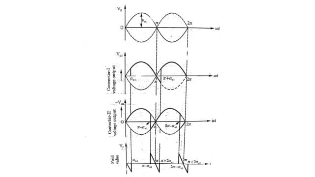
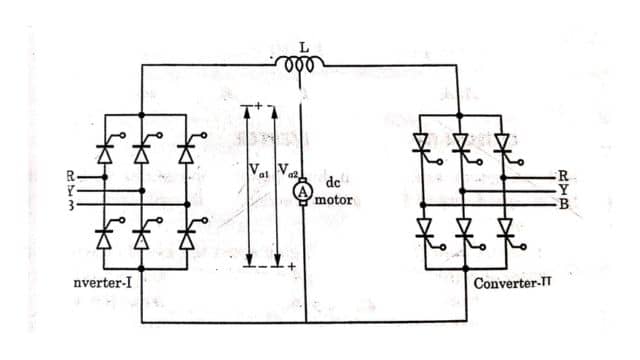
a1 + a2 = π When the reversal of output polarity is required, the firing angles of the two bridges are interchanged simultaneously so that bridge 2 Acts as a rectifier and bridge 1 as an inverter. The polarity of the rectifier will determine the polarity of the output DC voltage. As both the bridges operate simultaneously in this mode of operation, there is a continuous flow of circulating current between the two bridges That is why this mode is called circulating current mode. Due to this circulating current, power losses are increased. In order to reduce these losses an inductor Lis is introduced in the circulating current path. Even though the firing angles of the two bridges are adjusted, in such a manner that their average output voltages are almost the same. Still, there remains some difference in the instantaneous values of these outputs As the two fully controlled converters are connected back to back, both the voltage and current at the DC terminals can reverse and hence this dual converter can provide four quadrant operation as shown in Fig. Block diagram which shows the firing control of a dual converter in the figure. Single-phase dual converters are composed of two single-phase full-wave converters. These two full wave converters or Bridges are connected to the load or the motor. Converter 1 has four SCRs 1, 2, 3, and 4 and converter II has SCRs 5, 6, 7, and 8. When converter-I operates, the armature voltage is positive; when converter-II operates, the armature voltage is negative. Therefore, converter -I allow operation in the first and fourth quadrant while converter -II allows operation in the second and third quadrants. It is a four-quadrant drive and permits four modes of operation forward motoring, forward braking, reverse motoring, and reverse braking mode. Working: When converter -1 is gated. SCRs 1 and 2 are triggered in the positive half cycle of the input (L positive, N negative), the direction of the current flow is L (+ve) → SCR1 → A → Load → B→ SCR2 → N (-ve) Similarly, in the negative half cycle of the input, SCR3 and 4 are gated and the direction of the current flow is N (+ve) → SCR3 → A → Load → B → SCR4→ L (-ve) The direction of current through the load remains the same. Now, if the output polarity is to be reversed, after a dead time, converter -II is gated (in non-circulating current mode). The voltage waveform is shown in Figure. A three-phase dual converter consists of two three-phase full converters as shown in Figure. Converter -I provide a positive armature voltage to the drive while converter -II provides a negative armature voltage to it. Its four-quadrant operation and its principle are similar to the single-phase dual converter. When converter-I operates at a delay angle ai, then the average armature voltage will be Va1 = 3√3 / π. Vm cos aa1 When converter -II operates at a delay angle aa2, then the average armature voltage will be Va2 = 3√3 / π. Vm cos aa2 Due to the 3-phase full converter in the field circuit, the field voltage will be Vf = 3√3. Vm cos af (af = a1 + a2) Figure shows the average voltage profile for different firing angles for two converters Dual converters are used in high-power applications because they have the capability of speed control in both directions. Some applications of dual converters are given below. When the two full converters in antiparallel are connected to the same load, such an arrangement is known as a dual converter. It converts ac at one frequency to ac at another frequency. It is an electronic circuit that converts direct current(DC) to alternating current(DC). Read Also: 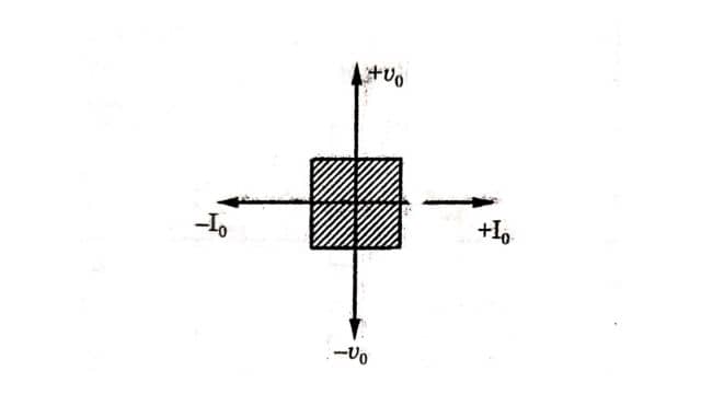
Single-Phase Dual Converter
Three-Phase Dual Converter
Application of Dual Converter
Frequently Asked Questions (FAQs)
What is a Dual Converter?
What is Cycloconverter?
What is Inverter?


Leave a Reply