Table of Contents
Full Wave Rectifier
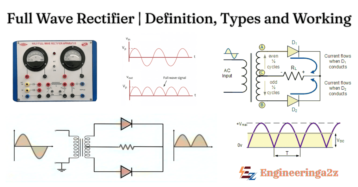
A full wave rectifier is a rectification circuit that is used to change the AC signal that is applied across its terminals into a pulsating DC form.
Rectification means conversion of AC signal into DC signal.
A full wave rectifier uses either 2 or 4 diodes in order to convert the applied AC signal into a DC signal.
Full Wave Rectifier Types
- Centre-tapped full wave rectifier
- Full wave bridge rectifier
1. Centre-Tapped Full Wave Rectifier
Centre-tapped full wave rectifier which is composed of centre-tapped transformer, whose secondary winding forms of a connection with anodes of two diodes D1 & D2. While the primary winding is provided with AC signal.
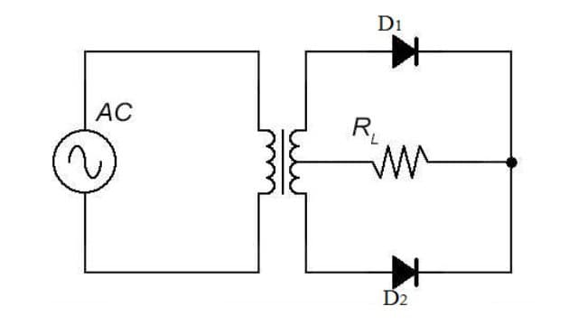
The cathode of two diodes are connected together with a load resistance RL & again with the centre of secondary transformer.
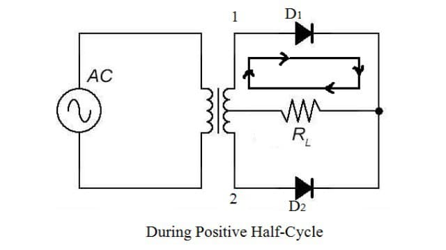
Working of Centre-Tapped Full Wave Rectifier
We apply an AC voltage to the input transformer. During the positive half cycle of AC voltage, terminal 1 will be positive cetre-tap will be at zero potential & terminal 2 will be negative potential. This will leads to forward bias in diode D1 and cause current to flow through it. During this time, diode D2 is in reverse bias and will block current through it.
During the negative half cycle of the AC input signal is provided to the diode then this second half cycle reverse biased the diode D1 but forward biased the diode D2. So, at this time diode D2 acts as a closed switch.
Thereby allowing current to flow at the lower region through the load resistance RL.
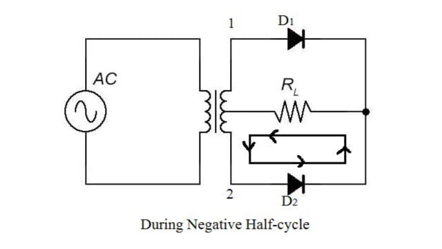
Thus, combinaly at the output, we achieve continues positive half cycle.
2. Full Wave Bridge Rectifier
A full wave bridge rectifier is a type of rectifier which will use four diodes in a bridge formation.
As we can see that this connections forms four junctions namely A, B, C, & D. So, junction A & C are connected to the secondary winding of the transformer. While the junction B & D are connected with the load RL.
Working of Full Wave Bridge Rectifier
We apply an AC voltage across the bridge. During the positive half cycle, terminal A becomes positive and terminal C become negative. This will cause the diodes D0 and D2 to become forward-biased and the current will flow through it. Meanwhile, diodes D1 and D3 will become reverse-biased and block current through them. The current will flow from A to B to D to C.
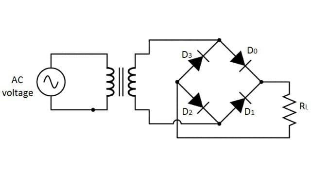
During negative half cycle, terminal A will become negative and terminal C will become positive. This will cause the diodes D1 and D3 to become forward-biased and the current will flow through it. At the same time, diodes D0 and D2 will be reverse-biased and will block the current through them. The current will flow from C to B to D to A.
Related Posts
- What is HDI PCB? And its Characteristics, Microvias and Advantages

- Waveguide | Types, Characteristics, Parameters, and Advantages

- USART (8251) : Universal Synchronous And Asynchronous Receiver-Transmitter

- UPS | Types | Comparison Between Online and Offline UPS

- Two Cavity Klystron Amplifier | Working, Operation and Performance

- TRIAC | Construction, Working and V-I Characteristics


Comments (1)
Hi there, I log on to your blogs like every week. Your writing style is awesome,
keep it up!