Table of Contents
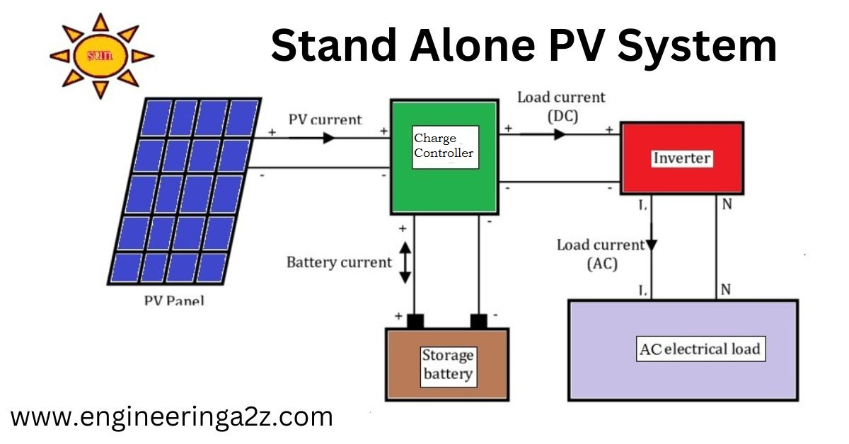
Stand Alone PV System
A standalone solar electrical system is one that uses only solar electric energy as its primary source of energy.There are many places on the planet where there is no power supply. In these cases, a standalone solar power system may be the best choice. The main advantage of this system is that it does not depend on grid or any other source of electricity.
Components Used in PV System
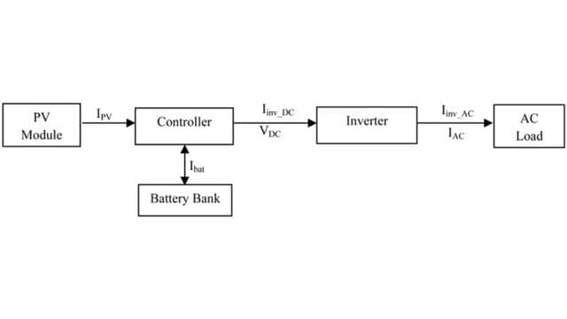
The stand alone pv system contain the following components.
- PV Generator
- Battery
- Controller
- Inverter
- Load
PV Generator
It is the combination of Solar cells, connections, Supports etc. In the present Modeling, the focus is only on Cell/ Module/ Array.
PV Cell Model
During Darkness the solar cell is not Working, it works as diode. It produces neither voltage nor a current, however if it is Connected to an external Supply. It generate a current ID Known as Diode current. Solar cell usually represented as.
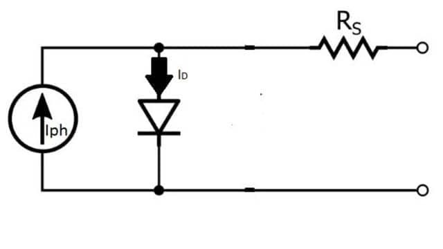
In this Iph is photo-current, ID is diode current and Rs is series resistance, which represents the resistance inside each cell. so, the current is the difference between the Iph & ID. i.e.
I = Iph – ID
PV Module Model
Cells are normally grouped into modules, which are covered with various materials to protect the cells and electrical connectors from the environment.
The manufacturers supply PV cells in modules, which consist of NP-parallel branches, each with NS-solar cells in series. Voltage at the module’s terminals is denoted by Vm, while the total generated current by the module is denoted by Im.
PV Array Model
The models in a pv system are typically connected in arrays. The applied voltage terminals are denoted by VA and the total current of the array is denoted by IA .
Battery
The battery is necessary in such a system because of the fluctuating nature of the output delivered by PV arrays. Thus, during the daytime or sunshine hours, the PV system directly feeds the load.
The extra energy is stored in the battery. During periods of low solar radiation, energy is supplied to load the battery.
Controller
All Power System must include a control strategy. The use of battery as a storage form, Implies during the Presence of Charge controller, The charge controller is use to manage the energy flow to PV system, batteries & loads.
Main Operating Modes of Controller
Normal Operating Condition
When the battery voltage fluctuates between maximum & minimum voltages.
Over Charge and Over Discharge Condition
when the battery voltage reaches some critical levels, i.e.
To protect the battery against an excessive charge, the PV array is disconnected from the system when the voltage increases above a certain value. PV arrays are connected again when the voltage decreases below a certain value.
To protect the battery against excessive discharge, the load is disconnected when the terminal voltage falls below a certain limit or value of voltage. The load is connected to the system when the terminal voltage is higher than a certain value.
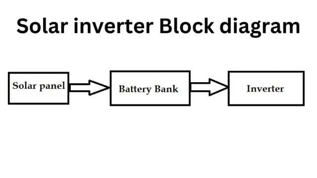
Inverter
As we know, the PV array produces dc power, and therefore, when a stand-alone PV system contains an AC load, it is required to convert dc to ac.
The inverter is characterized by a power-dependent efficiency. The role of the inverter is to keep the AC side voltage constant at the rated voltage of 220 volts.
Load
Load refers to the power consumption of the device used in the system. The load may be of many types both of DC and AC. AC load like electric heater.
Read Also :
- What is Solar Cell or Photovoltaic Cell
- Wind Energy
- B.Tech – MDU Previous Year Question Papers Download


Leave a Reply