Table of Contents
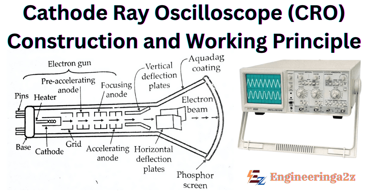
Cathode Ray Oscilloscope
CRO stands for Cathode Ray Oscilloscope. It is very useful and versatile laboratory instrument used for display, measurement and analysis of waveforms and other phenomena in electrical and electronic circuits. Cathode ray oscilloscope are used to infect very fast X-Y plotters, displaying an input signal versus another signal or input signal versus time. Cathode ray oscilloscope are also used to investigate waveforms, transient phenomena, and other time-varying quantities from a very low-frequency range to the radio frequencies. Cathode ray oscilloscope operate on voltages. However, it is possible to convert current, strain, acceleration, pressure and other physical quantities into voltages with the help of a transducer.
Construction of Cathode Ray Oscilloscope
Cathode Ray Oscilloscope consists of a cathode ray tube (CRT), which is the heart of the tube. The main parts of a CRT are :
- Electron Gun Assembly
- Deflection Plate Assembly
- fluorescent screen
- Glass Envelope
- Base for Connecting various parts.
1. Electron Gun Assembly
The electron gun assembly produces a sharply focused beam of electrons which are accelerated to high velocity. This focused beam of electrons strikes the fluorescent screen with high energy to cause a luminous spot on the screen.
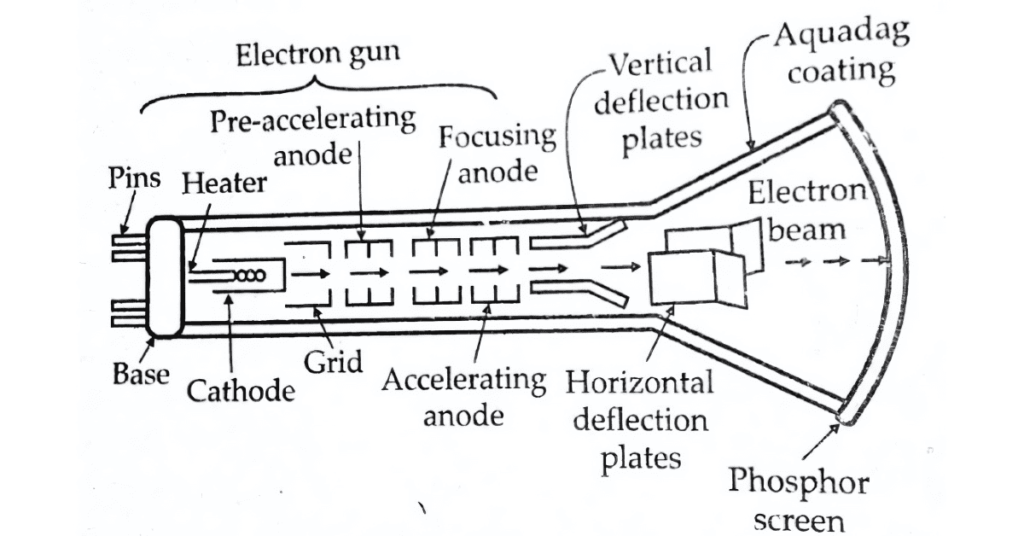
After leaving the electron gun, the electron beam passes through two pairs of electrostatic deflection plates. Voltages applied to one pair of plates move the beam vertically up and down and the voltage applied to the other pair of plates moves the beam horizontally from left to right and vice versa.
2. Deflection Plate Assembly
This explains the working of cathode ray oscilloscope; the electron beam, after leaving the electron gun, passes through two pairs of deflection plates. One pair of plate is mounted horizontally and produces an electric field in the vertical plane. This pair produces a vertical deflection and is thus called vertical deflection plates or Y-plates. The other pair of plates is called Horizontal Deflection Plates or X-Plates. The plates are flared so as to allow the beam to pass through them without striking the plates.
3. Fluorescent Screen
The front of the CRT is called the faceplate. It is flat for screen sizes up to about 100mm*100mm and is slightly curved for larger displays. The faceplate is formed by pressing molten glass in a mould and then annealing it. Some CRTs have a faceplate which is made from fibre optics, which has special characteristics.
The inside surface of the faceplate is coated with phosphor. This consists of very pure inorganic crystalline phosphor crystals about 2 – 3 microns in diameter to which traces of other elements called activators are added. Activator in current use are metals such as silver, manganese, copper and chromium. A phosphor converts electrical energy into light energy. When an electron beam strikes phosphor crystals it raises their energy level. This is called as cathodoluminescence. Light is emitted during phosphor excitation and this is called fluorescence. When the electron beam is switched off the phosphor crystals return to their initial states and release a quantum of light energy. This is called phosphorescence or persistence.
4. Glass Envelope
The working parts of CRT are enclosed in an evacuated glass envelope. So that the emitted electrons are able to move about freely from one end of the tube to the other end.
5. Base For connecting Various Parts
Through this, connections are made to various parts of the cathode ray oscilloscope. It is used to make external connections through pins.
Working Principle of Cathode Ray Oscilloscope
There are two methods of focusing an electron beam :
- Electrostatic Focusing
- Electromagnetic Focusing
The CRO uses electrostatic method of focusing as compared to a TV picture tube which employees electromagnetic focusing. So here we only discuss the Electrostatic focusing method.
Electrostatic Focusing
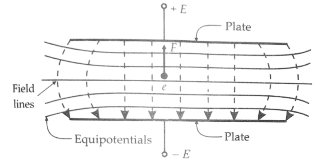
The figure shows an electron at rest placed in an electric field produced parallel plates. Force on the electron is,
F = – e. ε newton
where, ε = electric field intensity; V/m
and e = charge of electron = 1.602× 10⁻¹⁹ C
The minus sign indicates that the force acts in the opposite direction to that of the field. The above discussion is valid only if the electron is situated in a field of uniform intensity. In practice, however, the field is not uniform. The lateral repulsion of the electric field lines causes a spreading of space between the lines, resulting in curved field lines at the ends. Thus the field intensity will be less at the ends. The figure also shows equipotential surfaces, indicated by solid Lines.
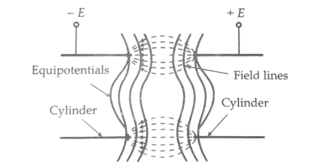
Since the force is in a direction opposite the field and the equipotential surfaces are perpendicular to the field, the force on an electron is in a direction normal to the equipotential surfaces. The figure shows two concentric cylinders with a potential applied between them. Lateral repulsion again causes the spreading of the flux lines producing a field as shown. The equipotential surfaces are shown as solid lines. It is clear from the below diagram that the equipotential surfaces are curved.
Related Posts
- BTech ECE Previous Year Question Papers PDF – Semester Wise Download

- Digital Electronics Notes PDF (Handwritten) | Engineeringa2z

- Pulse Code Modulation (PCM) | Block Diagram, Advantages and Applications

- What is HDI PCB? And its Characteristics, Microvias and Advantages

- Top 5 Benefits of Using Turnkey PCB Assembly

- How to Reduce PCB Assembly Costs Without Compromising Quality


Leave a Reply