Table of Contents
Ground Fault Indicators
In medium-voltage (MV) distribution networks, ground fault indicators (also called earth fault indicators or fault passage indicators, FPIs) help crews pinpoint single-phase-to-ground faults quickly so restoration can begin sooner. By providing a clear visual or remote signal that a fault current has passed a given location, FPIs narrow the search area, cut patrol time and reduce outage minutes.
What is a Ground Fault Indicator?
A ground fault indicator is a sensing and signalling device installed on feeders, in switchgear, or on lines. During a ground fault, the device detects characteristic current/field conditions and flips a mechanical target and/or LEDs; in some models, it also transmits the event to SCADA. The concept is straightforward: mark the last healthy point upstream of the fault so crews can bracket the damaged section.
Not to be confused with GFCI (ground-fault circuit interrupter) devices used in low-voltage buildings to protect people from shock by opening a circuit at small leakage currents. FPIs are grid-operations tools; GFCIs are personal-protection devices.
How do FPIs Detect Ground Faults?
Most FPIs sense the magnetic field produced by current in the conductor. Panel-mount and underground types often employ Rogowski-coil or CT-based sensors; overhead line indicators may clamp directly to the line. In grounded systems, a fault produces a distinctive increase in current; in isolated or resonant-earthed systems, indicators often look at the vector sum (zero-sequence) and detect imbalance. Newer devices can also communicate their tripped/reset state.
Why Utilities Deploy Them?
- Faster fault location — shorter SAIDI/CAIDI and lower operating costs.
- Fewer hazardous “fault-chase” operations — better crew safety.
- Better switching decisions with remote signalling devices
Indicator Types
- Overhead line FPIs — clamp-on, highly visible targets; some add radio/cellular.
- Underground/cable and switchgear FPIs — panel-mount with LEDs/flags, sometimes dry contacts or RS-485/Modbus for SCADA.
- Short-circuit + earth-fault combos — detect phase-to-phase and phase-to-ground events.
What to Consider When Selecting a Ground Fault Indicator
- System grounding: solid, high-resistance, or resonant (Petersen). Sensitivity and algorithms differ; low-current PtG faults demand low pickup and sometimes directional logic.
- Load profile & settings: choose pickup/hold times that avoid false trips on inrush or capacitive discharge.
- Installation point: panel/wall mount for MV switchgear vs. line-mounted for overhead.
- Indication & reset: mechanical flag + high-intensity LED; reset by time, manual pushbutton or remote/command.
- Communications: local-only or integrated (dry contacts/RS-485) for SCADA alarms.
- Environment & endurance: enclosure rating (e.g., IP65), temperature range, MTBF.
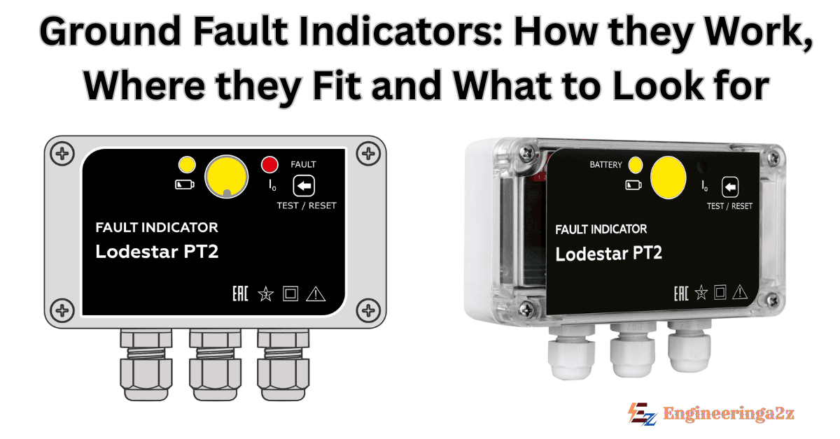
Product Example: Lodestar PT2 (short-circuit and earth-fault indicator)
For readers seeking a concrete reference design, the Lodestar PT2 is a panel/wall-mount short-circuit and earth-fault indicator for 6–35 kV distribution equipment. Key characteristics include: Rogowski-coil-based sensing, adjustable PtG pickup from 10 A, ultra-bright LED + mechanical flag indication, and multiple reset options (manual, time-based, external command/remote). The unit carries IP65 protection; auxiliary supply options include 110 V DC / 220 V AC-DC, with a standby lithium battery, and the stated MTBF ≥110,000 h. These attributes align well with typical MV switchgear applications; for remote signalling/SCADA, the related PRO variant adds RS-485 (Modbus).
Application Notes and Good Practice
- Tune sensitivity to grounding scheme. Isolated or resonant-earthed networks often require lower pickups and care with non-directional devices to avoid misoperations on capacitive discharge.
- Place indicators to “bracket” likely fault points. Pairing an upstream panel FPI (e.g., PT2) with downstream line devices shortens patrols.
- Document reset logic in switching procedures. Time-reset devices should be coordinated with restoration sequencing and reclose policy.
Frequently Asked Questions (FAQs)
-
Are ground fault indicators the same as GFCIs?
No. FPIs (MV network tools) signal where a fault current has passed; GFCIs (building safety devices) interrupt low-voltage circuits upon small leakage to protect people from shock. Different purpose, ratings, and standards.
-
Do indicators work in resonant-earthed (Petersen coil) systems?
They can, but setup is more demanding. Look for high sensitivity and, where needed, directional algorithms or zero-sequence measurements; avoid promising universal performance without confirming in-network conditions.
-
Where should I install FPIs for best results?
At strategic points that divide the feeder into segments (e.g., incoming switchgear, key junctions/cabinets, overhead taps). This “segmentation” lets crews quickly isolate the faulted span.
-
Can I integrate an indicator with SCADA?
-
What’s a good real-world example device?
The Lodestar PT2 for 6–35 kV switchgear combines adjustable PtG pickup, bright local indication (LED + flag), multiple reset modes, and an IP65 enclosure; a PRO version adds serial communications. It’s a practical example to reference when drafting specifications.


Leave a Reply