Table of Contents
Power Factor Meter
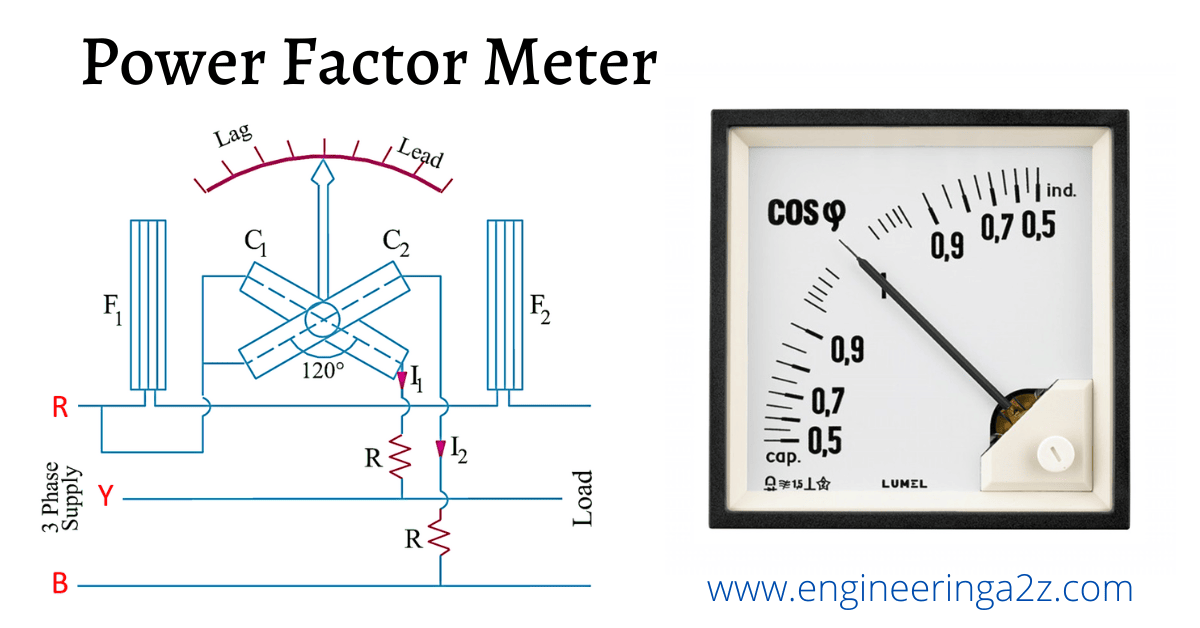
The instrument which is used for the measurement of power factor is called as power factor meter. The power factor may be defined as
- Cosine of the angle between voltage and current.
- The ratio of True power to the Apparent power.(V.I.cos φ/V.I).
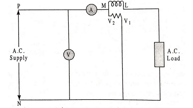
The figure shows an arrangement for determining the power factor of the load. The true power is measured by a wattmeter and the apparent power is calculated by the product of voltage and current, therefore the power factor of a single phase circuit can be calculated by noting down the reading of wattmeter, voltmeter and ammeter respectively.
Power factor meters have two circuits namely current and pressure circuit. The current circuit carries the load current or fraction of a load current whose power factor is to be determined and pressure circuit is split up into two parallel circuits, one circuit is non-inductive and the other is inductive. The deflection of the instrument depends upon the phase difference of the load current and the currents inn the two branches of the pressure circuit. i.e. upon the power factor of the load.
Types of Power Factor Meter
- Dynamometer type
- Moving Iron type
1. Single phase Dynamometer Type Power Factor Meter
The working principle of these type of measuring instruments is similar to that of a Dynamometer type wattmeter. As explained above it consists of two circuits.
- Current circuit
- Pressure circuit
Current circuit consists of two fixed coils CC connected in series with the load and carries the load current. The pressure circuit also consists of two identical coils P1 and P2 of fine wire pivoted at the same spindle and both are fixed at 90° to each other. The pressure circuit coil P1 is connected across the supply ends through a non- inductive resistance R and pressure circuit coil P2 is connected across the supply terminals through an inductance L.
The values of resistance and inductance are so selected, that for normal frequency, the current in both the pressure coils P1 and P2 are same. Since the current in both the pressure coils is the same, therefore, they will produce equally strong magnetic field which are 90° displaced from each other. If the phase displacement is not exactly 90°, it can be compensated by making mechanical angle between the two axis of coils P1 and P2 equal to electrical angle of difference between the two currents.
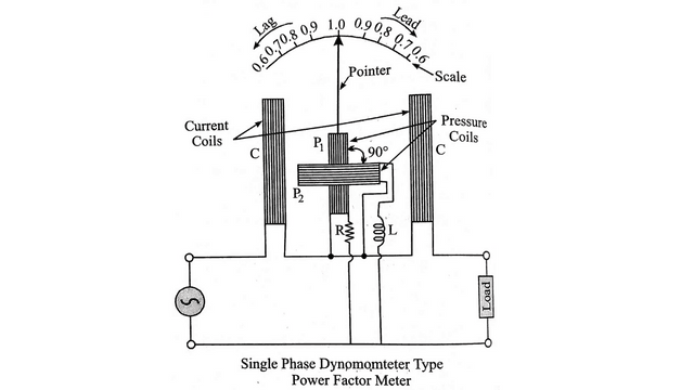
The pressure coils P1 and P2 form the moving system and they move together. A pointer is also attached with the moving system which indicates the power factor of the circuit directly. The instrument has no controlling torque, therefore the pointer remains in its deflection position.
Note : Zero adjustment in these type of instruments is not required.
Working of Power Factor Meter
When the instrument is connected in the load circuit, current flows through the current coils CC and pressure coils P1 and P2. The magnetic field is set up by all these four coils, due to the interaction of the fluxes, the turning moment or torque is produced. The moving coils start moving and turn to such a position that the resultant torque experienced by these coils is zero.
- Unity Power Factor : When the instrument is connected in the load circuit having unity power factor. The current in pressure coil P1 will be in phase with the load current or current in current coils CC and the current in pressure coil P2, will lag by 90֯ behind the voltage or behind the current in current coils CC. The coil P1 therefore will experience a turning moment and will adjust itself at a perpendicular to axis of CC and the pointer will indicate unity power factor.
- Lagging Power Factor : When the instrument is connected in the load circuit, having lagging power factor, in this case, both the pressure coils P1 and P2 would experience turning moments in opposite direction and therefore, the moving system will adjust itself at a position in between 0 and 1 depending upon the values.
- Leading power factor : When the instrument is connected in the load circuit having leading power factor, in this case, the polarity of field in current coils is the reversed of that considered above. Hence the moving system takes up an intermediate position on leading side in between 0 and 1.
Frequently Asked Questions (FAQs)
Why is moving iron power factor meter is generally used?
In moving iron power factor meter, all the energizing coils are stationary and there is electrical connection with the moving element. Thus the moving element can rotate through 360 degree giving scale extending over a full circle.
What is power factor?

It defined as the cosine of the angle between voltage and current is known as power factor. It may also be defined as the ratio of true power to the apparent power.


Comments (8)
Your style is very unique compared to other people I have read
stuff from. Thanks for posting when you have the opportunity, Guess I will just book mark this blog.
Good day! Do you know if they make any plugins to help with
SEO? I’m trying to get my blog to rank for some targeted keywords but I’m not seeing very good results.
If you know of any please share. Thanks!
Use Rank Math or Yoast Plugins
Excellent blog here! Also your website loads up fast! What host are you using?
Can I get your affiliate link to your host? I wish my web site loaded up as quickly as yours lol
Hosting Link: https://bluehost.sjv.io/c/3962837/795082/11352
whoah this blog is excellent i really like studying your posts.
Stay up the great work! You recognize, lots of persons are hunting around for this information, you can aid them greatly.
What’s up, I want to subscribe for this website to obtain latest updates,
thus where can i do it please help out.
Normally I don’t learn post on blogs, however I wish to say that this
write-up very pressured me to try and do it! Your writing style has been surprised me.
Thanks, quite great article.