Table of Contents
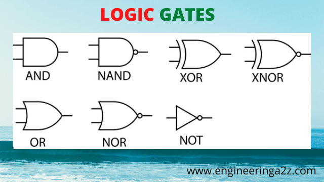
Logic Gates
Logic gates ate the basic building block of digital system. The term logic means to make decisions based on the combination of inputs. So, a logic gate is an electronics device which can make logical decisions. In case of a logic gate, there is only one output level which depends upon the combination of input levels. The value of inputs & outputs in logic gates can be 1 (High) and 0 (Low).
There are seven logic gates which are discussed in the later section.
- AND Gates
- OR Gate
- NOT Gate
- NAND Gate
- NOR Gate
- XOR Gate
- XNOR Gate
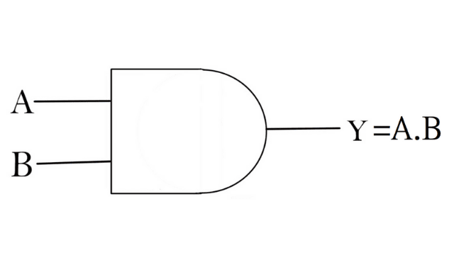
1. AND Gate
The AND gate can have two or more inputs and one output. The output of an AND gate is equal to the logical multiplication of inputs.
The logic symbol for AND gate is given below :
Truth Table
The truth table for AND gate is given below :
| A | B | Y = A.B |
|---|---|---|
| 0 | 0 | 0 |
| 0 | 1 | 0 |
| 1 | 0 | 0 |
| 1 | 1 | 1 |
Operation of an AND gate :
As the truth table for AND gate shows that the output (Y) is high (1) when both the inputs (A and B) are high (1). The output of AND gate is low (0) when any of the inputs (A or B) is low (0). The logical expression for two input AND gate output is
Y = A.B
2. OR Gate
The OR gate can have two or more inputs and one output. The output of an OR when any of the input is high (1). The output of a OR gate is low (0) when all the gate is equal to the logical addition of inputs. The output of a OR gate is high (1) inputs are low (0).
The logic symbol for OR gate is given below :
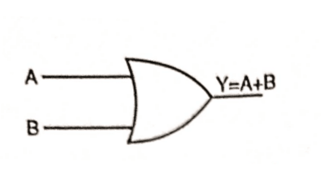
If the applied inputs are A and B, then the logical expression for OR gate given by
Y = A + B
Truth Table
The truth table for OR gate is given below :
| A | B | Y = A + B |
|---|---|---|
| 0 | 0 | 0 |
| 0 | 1 | 1 |
| 1 | 0 | 1 |
| 1 | 1 | 1 |
3. NOT Gate
It is called NOT gate because its output is always opposite to the input. It is also called an inverter because it invert the input signal. It has one input and one output. The inverter changes the one logic level to the opposite level. It changes a input 1 to output 0 and input 0 to output 1.
The symbol for NOT gate is given below :
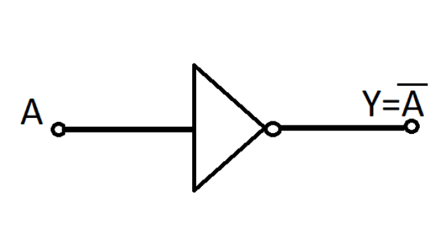
If the input at the NOT gate is A, then the logical expression for NOT gate output is given by
Y = A̅
Truth Table
| A | Y = A̅ |
|---|---|
| 0 | 1 |
| 1 | 0 |
4. NAND Gate
The NAND gate operation is equal to the NOT-AND operation. NAND gate is a combination of AND gate followed by an inverter.
The logic symbol for NAND gate is given below :
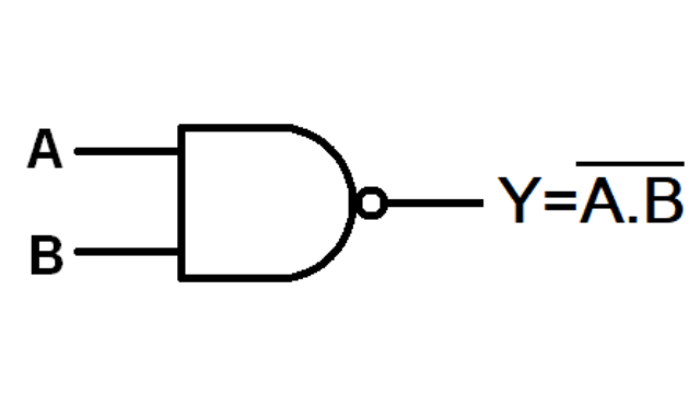
The logic expression for two input NAND gate is given by :

Truth Table
The truth table for two input (A and B) NAND gate is given below :
| A | B | Y=A͞.B |
|---|---|---|
| 0 | 0 | 1 |
| 0 | 1 | 1 |
| 1 | 0 | 1 |
| 1 | 1 | 0 |
Operation of NAND Gate
As seen from the truth table of two input NAND gate, the output of NAND gate is high (1), when any of the input is low (0). The output of NAND gate is low (0), when all the inputs are high (1).
5. NOR Gate
The NOR gate operation is equal to the NOT-OR operation. NOR gate is a combination of OR gate followed by an inverter.
The logic symbol for NOR gate is given below :
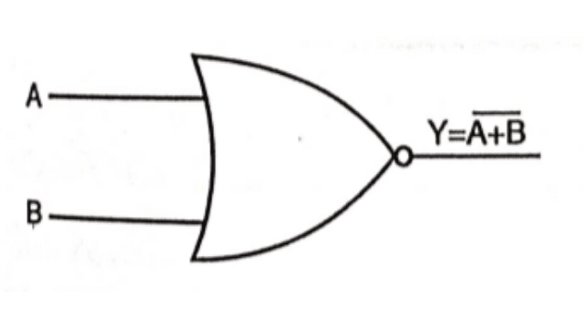
The logical expression for two input (A and B) NOR gate is given by :
Truth Table
The truth table for two input NOR gate is given below :
| A | B | Y |
|---|---|---|
| 0 | 0 | 1 |
| 0 | 1 | 0 |
| 1 | 0 | 0 |
| 1 | 1 | 0 |
Operation of NOR Gate
As seen from the truth table of NOR gate, the output is high (1), when both the inputs are low (0). When any of the input is high (1), then output is low (0).
6. XOR Gate (EXOR Gate)
It is two or more input and one output gate. This gate is widely used for designing digital circuits. The operation of XOR gate is performed by using basic gates NOT, OR, AND, NOR & NAND gates. XOR gate is widely used for building half adder, full adder, binary to gray code converter etc.
The logic symbol for XOR gate is given below :
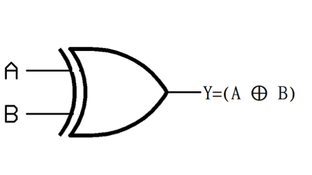
The logical expression for two input XOR gate is given by :
Y = A ⊕ B
Y = A̅B+AB̅
Truth Table
| A | B | Y = A ⊕ B |
|---|---|---|
| 0 | 0 | 0 |
| 0 | 1 | 1 |
| 1 | 0 | 1 |
| 1 | 1 | 0 |
Operation of XOR Gate
As seen from the truth table of two input XOR gate, is high (1). when both the inputs have different values means if AB = 01 or 10.
The output of XOR gate is low (0), when both inputs have same values which means if AB = 00 or 11.
7. XNOR Gate (EX-NOR Gate)
It is two or more input and one output gate. As the name implies it performs the complement operation of XOR gate. If we apply an inverter (NOT gate) at the output of XOR gate, then it becomes an XNOR gate.
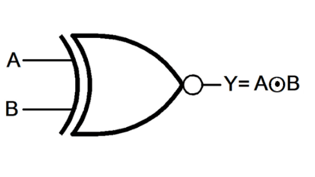
The logical expression for two input XNOR gate is given by :
Y = A ⊙ B
Y = A̅ B̅+AB
Truth Table
| A | B | Y = A ⊙ B |
|---|---|---|
| 0 | 0 | 1 |
| 0 | 1 | 0 |
| 1 | 0 | 0 |
| 1 | 1 | 1 |
Operation of XNOR Gate
As seen from the truth table of XNOR gate, the output of XNOR gate is high (1), when both the inputs are same which means when AB = 00 or 11. The output of XNOR gate is low (0), when both the inputs have different values which means when AB = 01 or 01. The XNOR gate widely used in the binary word comparator circuit.
Frequently Asked Questions (FAQs)
-
Why are NAND or NOR gates called as universal gates?
NAND and NOR gates are referred to as universal gates because they may be combined to create any of the other gates such as OR, AND, and NOT.
-
Write the OR gate’s Boolean expression?
The OR gate output can be written as Y=A+B if A and B are the inputs.
-
What is the equation of XNOR gate?
A ⊙ B is the expression for the XNOR operation between variables A and B. The truth table is once again satisfied by the equation Y=A̅ B̅+AB.


Comments (3)
Very soon this website will be famous among all blogging and site-building
viewers, due to it’s nice articles or reviews
Excellent blog here! Also your web site loads up very fast!
What host are you using? Can I get your affiliate link to your
host? I wish my site loaded up as quickly as yours
lol
Everyone loves what you guys tend to be up too. This type of clever work and
reporting! Keep up the good works guys I’ve incorporated
you guys to my blogroll.