Table of Contents
SCR Definition
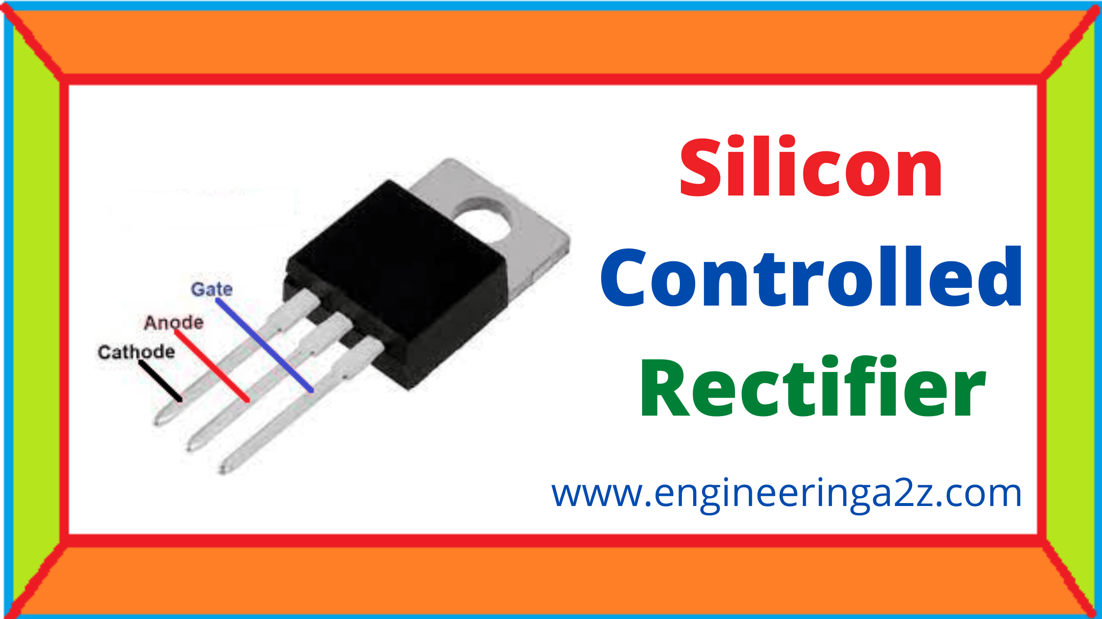
SCR is a four layer 3 terminal PNPN OR NPNP device it combine the features of transistor and a rectifier figure shows the construction circuit symbol of SCR.

it consists of two main terminals anode and cathode the third terminal gate is welded to the reason in between. It is widely used as switching device in power control applications it can switch on for variable length of time and delivers selected amount of power to load.
Construction of SCR
It consists of four layers and three terminals . The four layers made of P & N layers are arranged alternately such that they form 3 junctions J1, J2 and J3 . This junctions are either alloyed or diffused based on the type of construction.

The outer layers (P and N layers) are heavily doped whereas middle P and N layers are lightly doped. The gate terminal is taken at the middle P-layer. Anode is taken from outer P-layer and cathode is taken from N-layer terminal. The SCR is made of silicone because compared to germanium leakage current is silicon is very small. The junction J1 and J3 become forward biased while J2 is reverse biased.
Working of SCR
In a silicon controlled rectifier, the anode is always kept at positive potential with respect to cathode. The load is connected in series with anode. When no voltage is applied to the gate the junction J1 and J3 are forward biased whereas junction J2 is reverse biased. Thus, the condition of junction J1 and J3 is similar to NPN transistor with base open.
Hence, no current flows through the load and SCR is cut off. When the applied voltage is increased slowly, A stage reaches when junction J2 breaks-down. Due to break-down of j2 SCR conducts heavily and is said to be in ON state. The voltage at which breakdown occurs is known as breakdown voltage.

If a small positive voltage is applied to the gate, SCR conducts heavily at smaller applied voltage. The junction J3 becomes forward biased and J2 is reverse biased. The electrons present in N-type material moves across junction J3 to left side and holes in P-types material to right side. As a result, the electrons from junction j3 are attracted across junction J2 and gate current start flowing. With the flow of gate current, anode current increases. The rise in anode current makes more electron available at junction J2 .
This process continues and junction J2 breaks-down and SCR stars conducting heavily. When the SCR start conducting the gate loses its control. Anode current does not decrease even if gate voltage is removed.
V-I Characteristics of SCR
it is the graph between anode cathode voltage and anode current at constant gate current as shown in figure. It consists of two characteristics stages forward characteristics and reverse characteristics.

Forward Characteristics
when the anode is made positive with respect to cathode the graph plotted between V and I is known as forward characteristics. Forward characteristics of SCR for different values of gate current are shown in figure. If supply voltage is increased from zero value, a stage comes when SCR start conducting.
At this point most of supply voltage appear across the load and voltage across the SCR suddenly drops. If gate signal is applied the SCR start conducting at lower value of voltage. If now the gate signal is removed, the SCR remains ON. To turn the SCR OFF, the anode current will have to be reduced to certain minimum value known as holding current .
Reverse Characteristics
The curve between V and I, when anode is made negative with respect to cathode is known as reverse characteristics. When the reverse voltage is gradually increased, the anode current is small. After sometimes, a stage is reached where avalanche breakdown occurs and the stars conducting heavily in the reverse direction. The maximum value of reverse voltage at which SCR starts conducting heavily is called reverse breakdown voltage.
Frequently Asked Question (FAQS)
-
What are different methods of triggering of an SCR?
SCR triggering can be done by following methods :
1. Gate triggering.
2. Light triggering.
3. Temperature triggering
4. dv/dt triggering. -
What is the full form of SCR?
SCR stands for silicon controlled rectifier.
SCR is a four layer three terminal PNPN OR NPNP device it combine the features of transistor and a rectifier . -
Why SCR are mounted on heat sink?
SCR are mounted on heat sink in order to dissipate heat with minimum rise in junction temperature.


Comments (1)
Great 👍