Table of Contents
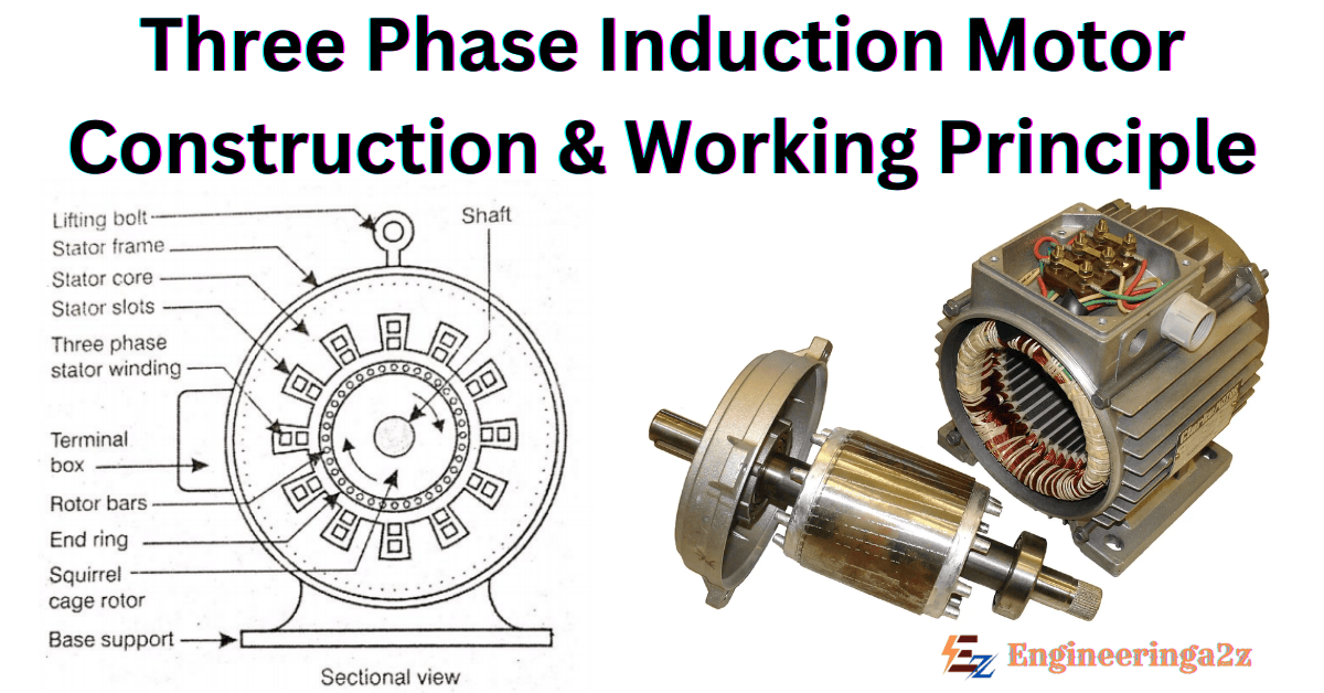
Three Phase Induction Motor
The three phase induction motor is one of the AC motors, which is widely used for various purposes in industry. These motors never run at a synchronous speed but a little less than the synchronous speed. The speed of these motors depends upon the supply frequency.
Therefore, these motors are not generally used for speed control. However, we prefer DC motors where large variations of speed are required. These motors are preferred in industry because they have low price, simple and rugged construction, can be manufactured with characteristics to suit the industrial requirement.
These motors differ from other types of motor, in that there is no electrical connection between the rotor and supply. The required voltage and current are induced by induction from the stator winding that is why, the name given is induction motor.
🔐 Download Handwritten Notes
- 3-Phase Induction Motor Handwritten Notes (PDF)
- Download here (Password protected)
- Get the PDF password from below link:
Construction of Three Phase Induction Motor
It can be better understood if we see the construction of three phase induction motor which has two major parts:
- Stationary part, known as Stator
- Rotating part, known as Rotor.
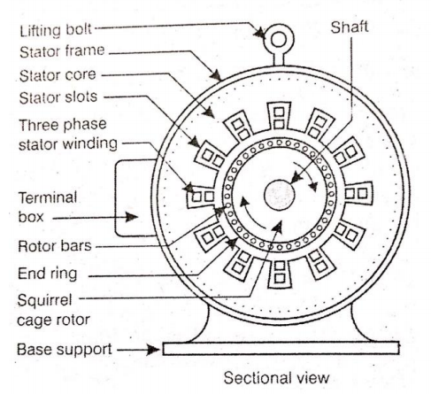
1. Stator
It is the stationary part of the motor. It has three main parts:
Frame or Yoke
It is the outer part of the three phase induction motor. Its main function of the frame is to support the stator core & stator winding. It acts as a covering, and it provides protection & mechanical strength to all the inner parts of the three phase induction motor.
Stator core
The main function of stator core is to carry the alternating flux. In order to reduce the eddy current loss, the stator core is laminated. The core is made up of thin silicon steel laminations. These are insulated from each other by varnish, the slots are cut on inner periphery of core stampings. The stator windings are placed in these slots.
Stator windings
Stator winding is made up of super enamelled copper wire. Three phase windings are placed in the stator core slots & six terminals are brought out. They may be star connected or may be delta connected. The windings are connected in star at starting.
2. Rotor
It is a rotating part of the motor. It is mounted on the shaft. It consists of hollow laminated core having slots on its outer periphery. The windings placed in these slots (rotor winding) may be one of the following two types :
- Squirrel cage rotor
- Slip ring rotor or wound rotor or phase wound rotor.
1. Squirrel cage rotor
The rotor consists of a cylindrical laminated core with parallel slots for carrying the rotor conductors. The squirrel cage rotor consists of a aluminium, brass or copper bars. These aluminium, brass or copper bars are called rotor conductors & are placed in the slots on the periphery of the rotor. The rotor conductors are permanently shorted by the copper, or aluminum rings called the end rings. To provide mechanical strength, these rotor conductors are braced to the end ring & hence form a complete closed circuit resembling like a cage & hence got its name as squirrel cage induction motor.

2. Slip ring rotor or wound rotor or phase wound rotor
The wound rotor consists a slotted armature. Insulated conductors are put in the slots & connected to form a three phase double layer distributed winding similar to the stator winding. The rotor windings are connected in star.
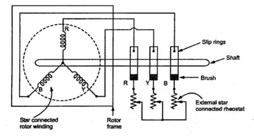
The open end of the start circuit are brought outside the rotor and connected to the insulated slip rings. The slip rings are mounted on the shaft with brushes testing on them. The brushes are connected to three phase variable resistors connected in star. The purpose of slip rings & brushes is to provide a means for connecting external resistors in the circuit.
Working Principle of a Three-Phase Induction Motor
The motor works based on electromagnetic induction, which means electricity is generated in the rotor without any direct electrical connection.
Rotating Magnetic Field
When three phase power is applied to the stator windings, it creates a rotating magnetic field. This field spins around the stator at a certain speed called the synchronous speed.
Synchronous Speed (Ns): The speed at which the magnetic field rotates. It depends on the frequency of the power supply (f) and the number of poles (P) in the motor.
Ns = (120 f) / P
Where:
- Ns = Synchronous speed in revolutions per minute (RPM)
- f = Frequency of the power supply in Hertz (Hz)
- P = Number of poles in the motor
Induction of Voltage and Current in the Rotor
The rotating magnetic field cuts across the rotor conductors (the bars in a squirrel cage rotor or the windings in a wound rotor) .
This induces a voltage in the rotor conductors, according to Faraday’s Law of Electromagnetic Induction.
Because the rotor conductors are short-circuited (either by the end rings or through external resistors) a current starts flowing in the rotor.
Torque Production
The current flowing in the rotor conductors creates its own magnetic field. This rotor magnetic field interacts with the stator’s rotating magnetic field.
The interaction of these two magnetic fields produces a torque (turning force) on the rotor, causing it to rotate.
Rotor Speed and Slip
The rotor never quite reaches the synchronous speed of the rotating magnetic field. If it did, there would be no relative motion between the field and the rotor conductors and no voltage would be induced.
The difference between the synchronous speed (Ns) and the rotor speed (Nr) is called slip.
Slip (s): The difference between synchronous speed and rotor speed, expressed as a percentage of synchronous speed.
s = (Ns – Nr) / Ns
Where:
- s = Slip
- Ns = Synchronous speed in RPM
- Nr = Rotor speed in RPM
Rotor Frequency
The frequency of the induced current in the rotor depends on the slip.
Rotor Frequency (fr):
fr = s f
Where:
- fr = Rotor frequency in Hz
- s = Slip
- f = Stator frequency in Hz
Advantages of Three-Phase Induction Motors
- Simple and Rugged Construction: They are built to last.
- Low Cost: Relatively inexpensive compared to other types of motor.
- High Efficiency: They convert a large portion of electrical energy into mechanical energy.
- Self-Starting: They start automatically when power is applied (squirrel cage motors) .
- Easy to Maintain: They don’t require a lot of upkeep.
Applications of Three-Phase Induction Motors
- Industrial Machinery: Pumps, fans, compressors, conveyors, machine tools.
- Power Generation: Driving generators.
- Transportation: Electric vehicles (traction motors).
- Household Appliances: Some larger appliances like washing machines and air conditioners.
Related Posts
- Electrical Machines Notes PDF (Handwritten) | Motors & DC Machines

- Lubrication: Principle, Types of Lubricants and Essential Properties
- Stepper Motors | Types, Parameters, and Characteristics
- Three Phase Induction Motor | Construction and Working Principle

- Static Phase Shifting Transformer | Configurations and Improvement

- Capacitive Voltage Transformer | Working, Characteristics, and Applications


Leave a Reply