Table of Contents
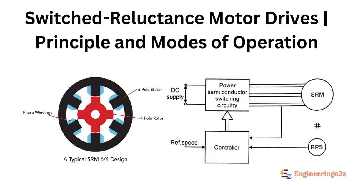
The Switched-Reluctance Motor Drives system combines a simple motor construction and an economic power converter circuit which offers a superior performance drive with high overall efficiency and quite flexible control characteristics. The switched- reluctance motor is being evaluated, nowadays, for applications ranging from low power servomotors to high power traction drives. Motors of power ratings varying from 4 to 22 kW are commercially available at present, for many applications.
Principle Operation of SRM Drives
The operation principle of switched-reluctance motor (SRM) drives can be illustrated through a one-phase winding of a 4-phase switched-reluctance motor having eight poles in the stator and six poles on the rotor. Both the stator and the rotor are of the salient-pole construction. While the rotor has no windings, each stator pole has a concentrated winding around it and each pair of diametrically opposite coils comprise one phase of the motor.
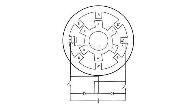
Torque produced by exciting any phase of the stator winding through unidirectional currents results in the magnetic attraction of an adjacent rotor pole as it tends to align into a position of minimum reluctance.
When the number of stator and rotor poles differ, the sequential switching of the excitation from one set of stator poles to the next, in synchronism with the rotor position, results in an almost constant torque causing uniform rotation. The synchronization of the switching on of the excitation with rotor position can be accomplished with simple rotor position feedback.
Nature of Torque Production
Neglecting the non-linearity of the magnetic circuit, the instantaneous torque developed in such machines can be expressed as :
T = 1/2 .i2 .dL/dθ
where i is the instantaneous current in the exciting winding and L, the self inductance of that winding varying as a function of the angular position of the rotor.
It may be noted that the torque created is independent of the direction of current flow in the windings, so that unidirectional currents can be used permitting simplification of driving power circuit configurations.
The figures show the ideal variation of the exciting winding’s inductance with respect to the angular position of the rotor over a periphery of one rotor pole pitch and the corresponding torque obtained for an assumed value of constant current (using Eqn. above). It can be seen that the torque can be controlled by appropriate switching on and off of the exciting current during the cycle of variation of inductance.
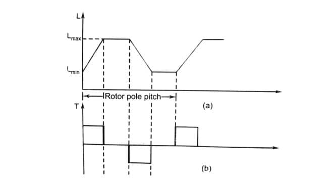
An average motoring torque is produced by switching on current pulses in each stator phase to coincide predominantly with the period during the inductance value is increasing. Thus, a rotor position sensor is a must to determine the switching instants for different phases.
If the switching is delayed such that the current pulse period coincides with the period at which the rate of change of inductance with position is negative, the torque produced will be negative and regeneration takes place. It may be worth noting that regeneration is achieved without any additional circuit elements. In fact, the possibility of operating in all four quadrants of the speed-torque plane and obtaining flexible speed-torque characteristics simply by appropriate switching of current pulses makes the motor very versatile.
Modes of Operation of the Motor
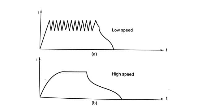
Modes of operation of the motor having two distinct modes operation exist, corresponding to low or high speed. It is essential to monitor the exciting current during low speed operation, since each phase period is of long duration and the energization must be ‘chopped to restrict each phase current within the semiconductor ratings. Moreover, control over torque produced is achieved by varying the mean phase current and, hence, accurate monitoring of the current is required to obtain the high degree of controllability possible.
At high speeds, current control is not necessary, since inductance of the winding and the motional counter emf induced restrict the excitation to single pulses of current. Torque control is obtained by optimal positioning of these pulses rather than the current level. Current monitoring, however, is retained for the sake of protection.
Figure show typical phase current waveforms for the above two modes of operation.
Thus, the complete drive system comprises a switched-reluctance motor coupled with a load, a power converter, and a control system involving a rotor position transducer and current sensor, as depicted in Fig.
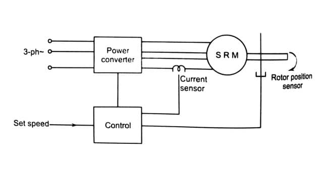
Power Converter
The power converter circuits used for energizing switched-reluctance motors have few semiconducting devices than the inverters feeding AC motors and those devices have only one forward voltage drop in series per phase so that the power losses may, in general, be lower than in conventional inverters.
Other factors being the same, the above facts should permit a reduction in the physical size of the converter and an increase in its reliability. Also, shoot-through faults are impossible because there is always a motor winding in series with each main power switching device.
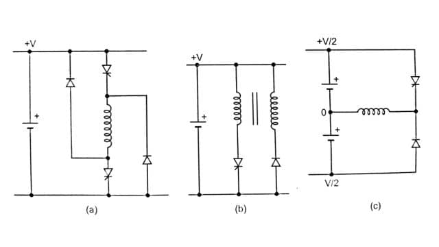
Different circuit configurations are available for the power converter for SRM drive, all of them having two essential elements-a controlled switch or switches to connect the direct voltage source to the exciting winding to build up current and an alternative path for the current to take when the switch is turned off. The latter is often provided by a diode or diodes such that the winding experiences a reverse voltage to collapse the current.
Figure shows three alternatives for one phase of an SRM power converter. A flexible circuit using two swithces per phase is illustrated in Fig., whilst the use of a bifilar wound motor (as in stepper motors) or a centre tapped supply allows the use of only a single switch per phase as shown in Figures. The correct choice of circuit configuration will depend on the drive power level, the supply voltage and the application.
Frequently Asked Questions (FAQs)
-
What is the application of SRM drive?
Switched reluctance motors work well in coal mining equipment like cutters and conveyors. They start with low current but produce high torque, even at 30% power.
-
What are the modes of SRM?
Switched reluctance motors (SRM) work in two modes: single-pulse and pulse-width-modulation. In single-pulse mode, each phase’s current rises quickly, creating torque as inductance increases.
Related Posts
- Paper Mill | Process, Requirements, and it’s Types

- Switched-Reluctance Motor Drives | Principle and Modes of Operation

- DC Motor Systems | Controlled Rectifier Circuits and Chopper Circuits
- Starting of Electric Drive | Effect, Methods, and Energy Relations

- Rating and Heating of Motors
- Drives | Types and Comparison Between AC Drives and DC Drives


Leave a Reply