Table of Contents
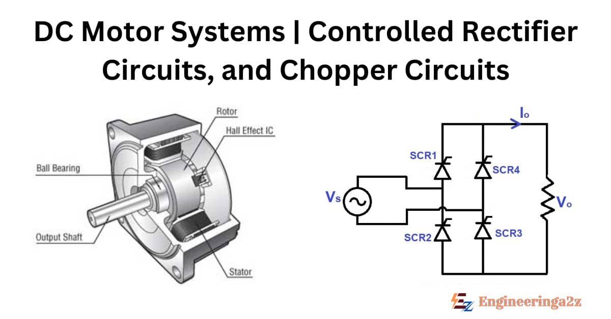
DC Motor Systems
Solid state control circuits have been developed for every single method used to change the speed-torque characteristics of a DC motor. Specifically, you can do this by adjusting the armature voltage, by adjusting the field current or by adjusting both together.
Adjustable armature voltage can be obtained either from controlled rectifier circuits (usually called converters) or from chopper circuits. Choppers are normally used when a stable DC supply is already available.
While motor voltage control is achieved in converter circuits by varying the phase angle (firing angle) at which the thyristors are triggered relative to the applied AC voltage waveform, it is obtained in chopper circuits by changing the on-to-off time ratio for which the dc supply voltage is applied to the motor terminals. Instead of complex converter circuits, it is also possible to use a simple uncontrolled rectifier, which gives a constant direct voltage, followed by a chopper circuit to provide a variable mean direct voltage output. Any variation needed in the field current can be obtained by supplying the field winding from an auxiliary small-scale controlled rectifier circuit.
1. Controlled Rectifier Circuits
Rectifier circuits are classified according to the number of output voltage pulses they produce during one full period of the AC line power frequency. The simplest converter has m = 1, where m equals the number of voltage pulses per cycle of the supply voltage.
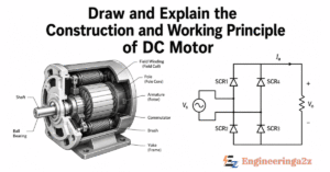
The basic forms of these converters are shown in standard power electronics schematics. Let’s look at a DC motor fed by such a single-pulse converter. During standstill conditions of the motor (when the motor is stopped), when terminal S1 is more positive than S2, the thyristor (TH) may be gated on (fired), producing the output voltage and current waveforms.
That means during the positive half cycle of the supply voltage waveform, the current flows directly from the source into the motor armature circuit. At the start of the negative half cycle, due to the reverse bias applied to the thyristor, the current would stop immediately if the armature circuit were purely resistive. However, since real armature circuits have appreciable inductance, during the negative half cycle although S2 becomes more positive than S1 current continues to flow from the source into the armature until the stored inductive energy is completely dissipated.
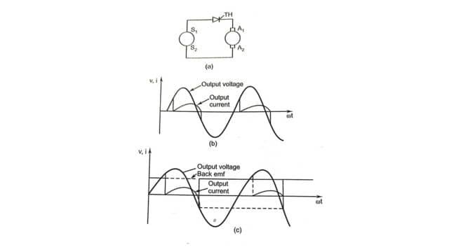
Operation of a 1-Pulse Converter Under Running Conditions
During running conditions of the motor, the thyristor can start conducting only when the instantaneous value of the ac source voltage becomes equal to or exceeds the back-induced emf (Eb) in the armature and when it receives a proper gating pulse. The thyristor reaches its blocking state (turns off) when the armature inductance has fully discharged its stored energy and the current falls to zero, just like during standstill conditions. The presence of the induced back emf, however causes a different output voltage waveform shape.
If the motor were driven by an external load connected to its shaft such that terminal A2 becomes positive concerning terminal A1, power would flow backward from the motor armature to the AC source line. This mode of operation is known as inverting.
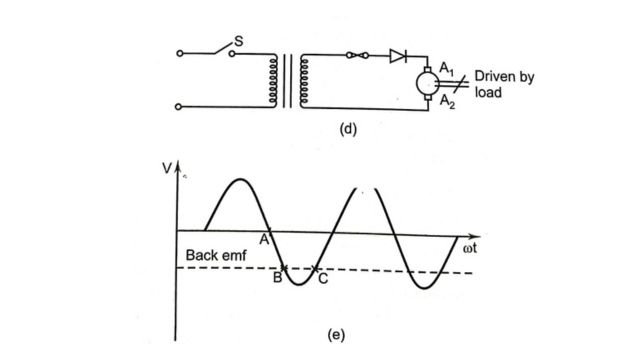
If during this inverting operation the main AC supply should fail (indicated by opening the switch S), there would be no AC source to naturally commutate (turn off) the DC current. Due to the very small circuit impedance, when switch S opens, the armature current continues to flow and increase rapidly until the fuse blows, the thyristor opens or the motor fails completely.
Another possibility of failure during inverting operation exists when the magnitude of the induced emf of the motor becomes too large concerning the AC line voltage. As shown in circuit waveforms, the thyristor begins to conduct at point 4. At points B, the AC line voltage and the induced emf impress a negative anode voltage on the thyristor, but due to the high inductance of the motor armature, the current continues to flow anyway. At point C, the AC line voltage and the induced emf produce a positive anode voltage, so the thyristor continues to conduct. The armature current continues to increase during successive half cycle periods until circuit failure occurs.
1-Pulse Converter with Freewheeling Diode
We can also look at another form of a single-pulse converter that includes a freewheeling diode. This circuit, because of the presence of the freewheeling diode, cannot feed energy back into the ac line.
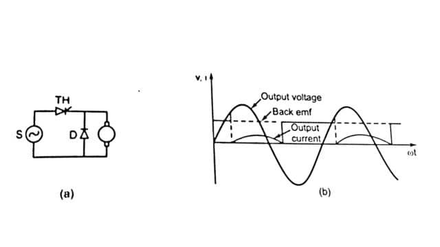
During the negative half cycle, energy stored in the armature inductance flows from the armature through the freewheeling diode at a negligibly small voltage drop. Hence, the conduction of current during the negative half cycle is for a much longer period. The form factor (the ratio of RMS current to average value) of the armature current is lower and much more stable.
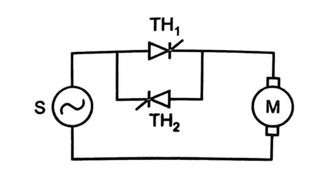
Reversible 1-Pulse Converter and Multi-Phase Systems
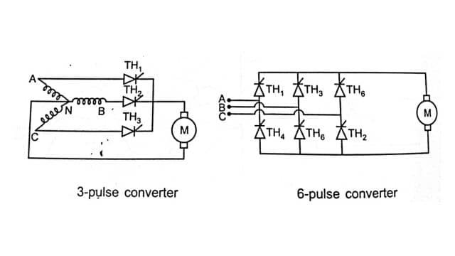
Three-phase rectifier circuits give more voltage pulses per cycle of supply frequency. This ensures the flow of armature current over a much longer portion of the cycle, which increases the form factor and reduces the internal heating of the armature winding. Also, the power is drawn from a balanced three-phase system, which generally has a much higher capability of supplying power than a simple single-phase system.
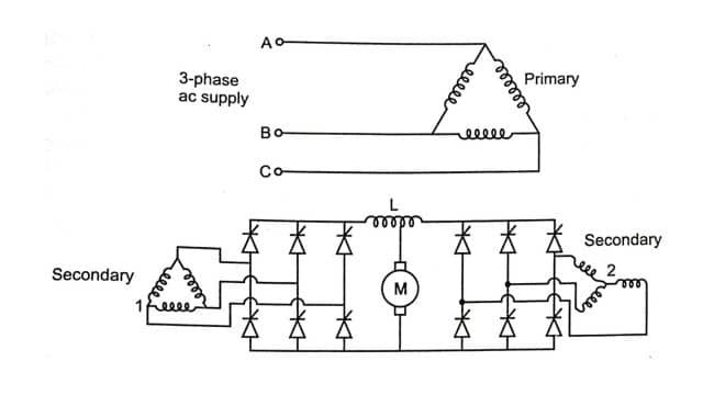
The commonly used three-phase rectifiers for industrial DC motor drives are categorized by their pulse numbers: m = 3 (3-pulse), m = 6 (6-pulse) and m = 12 (12-pulse).
The purpose of the interphase reactor (L) in the 12-pulse converter circuit is to permit each individual 6-pulse converter to operate independently in its normal manner. Each 6-pulse converter is completely isolated from the other. This type of high-end converter is used with large industrial motors to reduce the current ripple to a value much less than what you get with a standard 6-pulse converter.
The rectifier systems may be connected back-to-back in order to create reversible drives. This connection ties the positive output of one rectifier set to the negative output of the other. This allows motor armature current to flow in either direction for forward or reverse running. The main problem that must be overcome with this back-to-back connection is to prevent both sides of the converter from coming on at the same exact time, which would cause a direct short-circuit across the ac line.
The commonly used techniques to limit this short-circuit current are :
- Insertion of a heavy reactor (inductor) in the armature circuit.
- Providing a strict time delay before turning on the opposite rectifier.
- Introduction of an automatic current sensing device which completely prevents one side from turning on if current is still flowing in the opposite side.
2. Chopper Circuits
Chopper circuits are used to control the speed of motors which are fed from fixed voltage DC sources like batteries or uncontrolled rectifiers. A basic chopper circuit supplies a variable direct voltage to a series-wound motor.
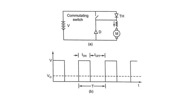
The input to the chopper is a fixed direct voltage (V). Here, the thyristor acts as a high-speed switch which is made ON and OFF at the rate of several hundred hertz. The relative on-to-off time ratio of the thyristor determines the mean (average) output voltage.
A variable output voltage can be obtained by varying this on-to-off time ratio (sometimes called the mark-space ratio). This is done either by:
- Adjusting the frequency of switching while keeping the on-time constant.
- Adjusting the on-time while keeping the switching frequency constant.
- Adjusting both the on-time and the frequency together.
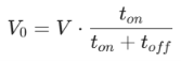
The average output voltage (V0) is calculated using the time parameters :
The thyristor cannot naturally turn off on its own while carrying DC current. Hence, it requires a specialized commutating circuit which applies a temporary negative anode to cathode voltage across the thyristor path for a short period to force it off. The commutating circuit is represented by a switch. The freewheeling diode provides a safe path for the armature current to keep flowing while the main thyristor is not conducting.
Three chopper circuits commonly used for obtaining variable direct voltage from fixed voltage sources are described below:
(a) The Morgan Chopper:
The Morgan chopper is a classic example of Class B commutation, which means it uses self-commutation via a resonating circuit helped by a saturable reactor. The greatest advantage of this circuit is that it needs only one single thyristor.
Therefore, the on-time (ton) is completely fixed by the LC parameters and the average voltage across the motor is varied simply by adjusting the chopping frequency. The gating oscillator generates this variable frequency.
When the main thyristor TH is fired, the capacitor C (which has a positive polarity at the dot mark in the schematic) discharges around the closed path formed by C – TH – L to reverse its state and acquire a negative polarity. As the current tries to reverse again, the voltage across the reactor is held up for a short time until saturation occurs. Once it saturates , the entire capacitor voltage appears directly across the thyristor.
The thyristor gets reverse-biased and if this discharge current is greater than the running thyristor current, it turns off completely. The capacitor continues to carry the load current until it charges up fully with the dot positive again. The freewheeling diode offers a path to dissipate further stored inductive energy; if the energy is fully dissipated before the thyristor is turned on again, the motor will temporarily coast.
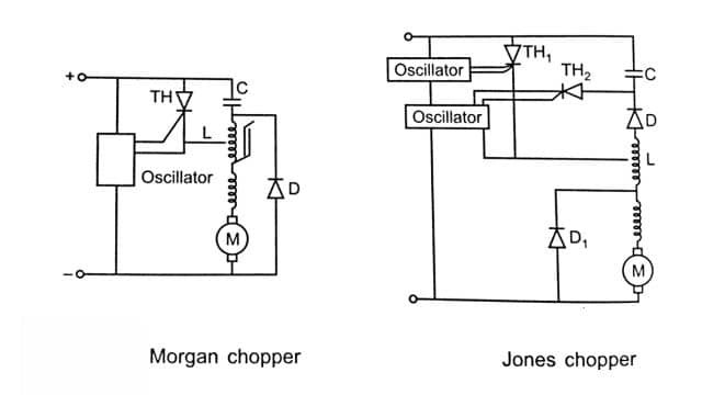
(b) The Jones Chopper:
The Jones chopper circuit is characterized by Class D commutation. A pre-charged capacitor C, switched by an auxiliary smaller thyristor (TH2) and an autotransformer (T) constitute the commutating circuit.
Although, in principle, both the on-time and off-time can be varied due to the presence of TH2, usually the off-time or total period (T) is varied using the gating oscillator of the main thyristor TH1, while keeping the on-time fixed using the oscillator of TH2 .
When the main thyristor TH1 is fired, the capacitor (which is charged positively at the dot) discharges around the circuit formed by C – TH1 – L – D and reverses its polarity. The blocking diode D prevents further resonance oscillations in the LC circuit. Hence, capacitor securely retains its reverse charge until the auxiliary thyristor TH2 is switched on.
When TH2 is turned on, the sudden discharge causes the main thyristor TH1 to be reverse-biased and turn off. The capacitor then charges back up with the dot positive again and TH2 turns off naturally since the current through it falls below its required holding value once the capacitor is fully recharged. The process repeats itself when TH1 is switched on again.
Even if the capacitor has not charged up fully by the time TH1 is switched on again, no damage is done. This is because load current ensures that the induced emf in the autotransformer winding L gives the capacitor sufficient commutating energy anyway. Due to this voltage boost, however the thyristors must be rated at a higher voltage capability.
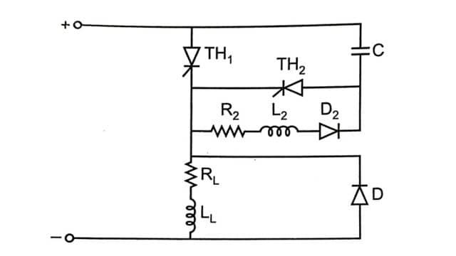
(c) The Oscillation Chopper:
The oscillation chopper circuit derives its name from the naturally resonating or oscillating nature of its class D commutation network. This basic circuit differs from both the Morgan and Jones choppers because there is neither a saturable reactor nor an autotransformer placed in the primary load circuit.
In this system, the auxiliary thyristor TH2 must always be triggered first so that the capacitor C can get fully charged with the dot positive. Then, when the main thyristor TH1 is switched on so that load current can flow to the motor, capacitor C reverses its polarity through the resonating path formed by C – TH1 – R2 – L2 – D2.
The capacitor remains locked in that reverse-charged condition because of the blocking diode D2 until TH2 is fired again. Firing TH2 discharges C rapidly, causing the main thyristor TH1 to become reverse-biased and turn off.
In choosing one power control circuit over the other, the following points should be borne in mind.
- Power supply: (a) dc (b) ac-single phase or three phase.
- From factor for the motor: (a) rectifier type (b) need of a choke.
- Need for inversion.
- Need for reversal.
- Necessity of a transformer either because of AC line voltage available or rectifier used.
- System cost: (a) transformer (b) choke (c) rectifier (d) motor.
- Electrical energy costs (a) rectifier power factor (b) rectifier efficiency.
- Amount of AC line pollution caused by the rectifier.
Frequently Asked Questions (FAQs)
-
How does a DC motor work?
When a DC motor is powered, the stator creates a magnetic field that pushes and pulls the rotor’s magnets, making it spin. The commutator keeps it rotating.
-
What is the role of a freewheeling diode in a DC motor converter circuit?
A freewheeling diode provides a continuous path for the armature current to dissipate its stored inductive energy when the main thyristor is turned off. This prevents massive voltage spikes and improves the current form factor, which reduces motor heating.
-
What is the difference between the Morgan chopper and the Jones chopper?
The Morgan chopper uses Class B self-commutation with a single thyristor and a saturable reactor, meaning its ON-time is fixed. Jones chopper uses Class D commutation with an auxiliary thyristor and an autotransformer, providing more control over the switching cycle.
Related Posts
- Explain Construction and Working of Autotransformer
- Single Phase Induction Motor | Double Revolving Field Theory

- Draw and Explain the Construction and Working Principle of DC Motor
- Difference between Synchronous Motor and Induction Motor

- No load or Blocked Rotor Test on Three Phase Induction Motor

- Electrical Braking System


Leave a Reply