Table of Contents
Two Cavity Klystron Amplifier
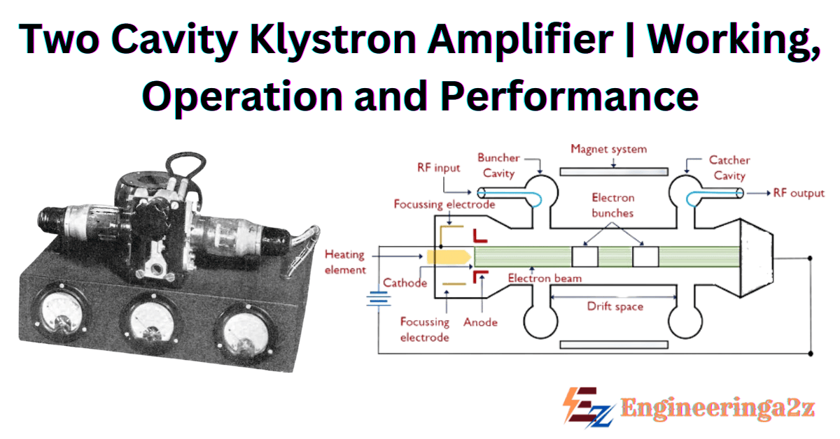
The two-cavity klystron is a widely used microwave amplifier operated by velocity and current modulation principles. It consists of an electron gun, focussing and accelerating grids, two identical cavities separated by a distance and at the far end a grounded collector plate. The electron gun emits electrons from its cathode’s source and then focussed into a beam. Using a dc accelerating positive voltage the beam is accelerated to high velocities.
Working Principle of Two Cavity Klystron Amplifier

It operates by the principle of velocity and current modulation. It consists of two cavities as shown in the fig. The cavity close to the cathode is known as Buncher Cavity or Input Cavity, which velocity modulates the electron beam. The other cavity is known as Catcher Cavity or Output Cavity catches energy from the bunched electron beam.
The two-cavity klystron is a microwave frequency amplifier which operates on the principles of velocities and current modulations. All electrons injected from the cathode arrive at the first cavity with uniform velocity. Those electrons passing the first cavity gap at zeros of the gap voltage (or signal voltage) pass with their velocity unchanged. Electrons passing during the positive half cycles of the gap voltage undergo an increase in velocity; those passing through the negative swings of the gap voltage undergo a decrease in velocity.
As a result, the electrons gradually bunch together as they travel down the drift space. The variation in electron velocity in the drift space is known as velocity modulation. The electron destiny in the second cavity gap varies cyclically with time. The electron beam contains as a component and is said to be current-modulated. The maximum bunching should occur approximately midway between the second cavity grids during is retarding phase. The kinetic energy is transferred from the electrons to the field of the second cavity. The electrons emerging from the second cavity have reduced velocity and are collected by the collector.
You may also like


Operation of Two Cavity Klystron Amplifier
The RF signal which is to be amplified is used to exciting the input buncher cavity thereby developing an alternate voltage of signal frequency across the gap A. The signal will initiate an electromagnetic field inside the cavity . Electron are generated from cathode terminal and move toward buncher cavity. In buncher cavity, there is already a signal feeded which is to be amplified. Interaction between electrons and RF signal take place. Because of which bunching take place. Electrons which passes through zero of the RF signal, no change is velocity occurs. Electrons which passes, when signal at positive potential, velocity of electrons increases.
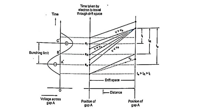
Electrons that pass, when signal at negative potential, velocity of electrons decreases. In this way velocity modulating take place. And bunches formation takes place. During bunches, electrons gain too much high energy. This is released when these bunches passes through catcher cavity during the retarding phase of the signal. Output is taken from the catcher cavity with the help of coupling loops. At Point B’ on the input RF cycle, the alternating voltage is zero.
At this instant, electric field across gap A is zero and electron that passes through gap A at this instant is unaffected by RF signal, This electron be called reference electron (er) which travels with unchanged velocity (v0). At Point C’ of the input R cycle an electron that leaves gap A later then reference electron er, called late electron el is subjected to maximum positive RF voltage and hence travels toward gap B with an increased velocity (v> v0 ). This electron tries to overtake the reference electron. Similarly, early electron ee that passes the gap A slightly before the reference electron is subjected to maximum negative field.
Hence this electron is deaccelerated and travels with a reduced velocity. Therefore the velocity of electron varies in accordance with RF input voltage, resulting in velocity modulation. Bunches electrons travel down the drift space, from gap A to gap B. Drift space converts the velocity modulation into current modulation. Bunching occurs only once per cycle centered around the reference electron. A little RF power applied to the buncher results in large beam currents at the catchers cavity with considerable power gain.
Characteristics of Two Cavity Klystron Amplifier
The characteristics of a two-cavity klystron amplifier are as follow:
- Efficiency:- about 40%
- Power output:- average power is up to 500 kW and pulsed power is up to to 30 MW at 10 GHz.
- Power gain: about 30 dB.
Applications of Two Cavity Klystron Amplifier
- Television Broadcasting: Used in television transmitter, especially for uhf channels.
- Medical application: Its found in medical devices such as linear accelerators for radiation therapy.
- Satellite Communication: Amplifier microwave signals for uplink and downlink in satellite communication systems.
- Radar Transmitters: It is used as a high power RF amplifier in radar transmitter for military, weather, and aur traffic control systems.
Frequently Asked Questions (FAQs)
-
Who invented the Klystron?
The brothers Russell and Sigurd Varian of Stanford University are the inventors of the klystron. Their prototype was completed in August 1937.
-
What are the advantages of two cavity klystron amplifier?
– It operates at higher efficiencies.
– In two cavity klystron, each cavity operates independently and there is no mutual coupling.
– It improves power o/p, efficiency and klystron amplifications. -
What are the drawbacks of two-cavity klystron amplifiers?
– It can be used at only one operating frequency.
– Two cavity klystron is not low-noise device. Due to this effect, usually it is used in the transmitter and not in the receiver. -
Why is called Klystron?
It was named “Klystron” after an ancient Greek verb indicating waves washing on a shore.
Related Posts
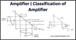
- Amplifier | Classification of Amplifier
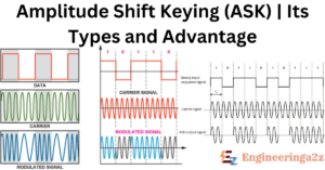
- Amplitude Shift Keying (ASK) | Its Types and Advantages
- B.Tech – Electrical Engineering Previous Year Question Papers Download

- Bipolar Junction Transistor (BJT): Types, Working, Construction, Advantages

- BTech ECE Previous Year Question Papers PDF – Semester Wise Download

- Cathode Ray Oscilloscope (CRO) Construction and Working Principle


Leave a Reply