Table of Contents
Introduction
A three-phase induction motor has a kind of electrical “resistance” when it starts, which makes it draw too much electrical current when you turn it on. This can be dangerous and harmful to the motor. To prevent this, we use special devices called starters.
Starters help the motor start safely and prevent it from taking too much current. But for small motors, this is usually not a problem because they have some built-in resistance and start quickly.
Induction motors are commonly used in industry because they are tough, cost-effective, and don’t have parts that wear out easily. However, controlling their speed can be tricky. They don’t change speed easily when you want them to. But with modern electronics and digital control systems, we can now use them in more types of applications where we need to control the speed with different loads.
In simple terms, induction motors are great for many jobs, but getting them to change speed precisely used to be tough. Now, with new technology, we can make them work well in more situations.
Starting Methods Of Three-Phase Induction Motors
Think of an induction motor as a special type of transformer with its secondary part (like the output) connected to itself. When you first turn it on with the normal power supply, just like in regular transformers, it pulls a lot of electricity for a short time. This happens because, unlike DC motors, induction motors don’t have a special resistance that limits their initial current.
If you switch on a big induction motor directly from the power supply without any control, it can draw 5 to 7 times more electricity than it normally uses when it’s running at full power. But here’s the problem: even though it’s using a lot of electricity, it doesn’t create much twisting power (torque) to start spinning.
This big surge of electricity also causes a drop in voltage in the electrical line, which can mess up the operation of other devices connected to the same line. So, it’s not a good idea to turn on big induction motors (usually over 25 kW) directly from the main power supply.
To deal with this, we have different ways to start these motors more safely and smoothly.
1. Direct-On-Line (DOL) Starters
Small three-phase induction motors can be started directly by connecting them straight to the power supply. However, when you do this, the motor pulls a lot of current when it starts, which can be 5 to 7 times more than what it normally uses. Also, it might not provide enough power to get things moving, producing only 1.5 to 2.5 times the usual twisting force.
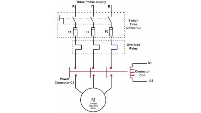
To handle this, we use something called a DOL (Direct-On-Line) starter. It’s made up of a switch called a contactor and a safety device like a circuit breaker. The contractor is like a remote control for the motor. When you press the “start” button, the contactor switches on and connects all three power phases to the motor at once, making it start running. When you press the “stop” button, it turns off and disconnects the motor from the power supply, stopping it.
We use DOL starters mainly for motors that are smaller, usually below 5 kW, to avoid causing a big drop in voltage in the power supply when they start up.
2. Starting Of Squirrel Cage Motors
To prevent a sudden surge of electrical current when starting up squirrel cage motors (the kind of motors commonly used in many appliances), we use methods that reduce the initial voltage applied to the motor’s main part, called the stator. These methods are often referred to as “reduced voltage methods” for starting squirrel cage induction motors. There are a few ways to do this:
- By using primary resistors
- Autotransformer
- Star-delta switches
(i). Using Primary Resistors
Primary resistors are used to lower the voltage that goes to the main part of a motor (called the stator) when it starts. Imagine we reduce the starting voltage by 50%. According to Ohm’s law (which deals with how electricity works), the starting current also goes down by 50%.
Now, there’s a formula for the power (twisting force) a motor can generate, and it tells us that the starting torque (twisting power at the beginning) is roughly related to the square of the voltage we apply. So, if we lower the voltage to just 50% of what the motor normally gets, the starting torque drops to only 25% of its usual value.
This method is commonly used for gently starting small motors. But be cautious; it’s not suitable for motors that need a lot of torque to get going because it won’t provide enough power.
Here’s how it works: At the start, we connect full resistance (like a barrier to electricity) in line with the stator. Then, as the motor speeds up, we gradually reduce this resistance. When the motor reaches a certain speed, we remove the resistors completely, and the stator gets full power from the supply lines.
So, in simple terms, primary resistors help small motors start smoothly by gradually increasing their power to, but they’re not great for big motors that need a lot of power right from the start.
(ii). Autotransformer
An auto-transformer, sometimes called an auto-starter, is a handy device used to start both star and delta-connected squirrel cage motors (these are common types of electric motors). It’s like a special kind of transformer that can lower the power going to the motor when it starts.
Think of it as having different settings, like on a volume control. You can set it to start the motor at 50%, 65%, or 80% of the regular power. When you use this auto-transformer, the electricity drawn from the power supply is always less than what the motor needs because of how the transformer works.
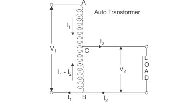
For example, if you set it to 65%, the motor gets 65% of the regular power, and the current it uses is also 65% of what it normally takes. But here’s the cool part: the electricity coming from the power supply is even less, like 42%. This difference happens because of the transformer magic.
Inside the auto-starter, there’s a switch. When you start the motor, you put the switch in the “start” position, and the motor gets the reduced power you set. As the motor speeds up, let’s say to 80% of its normal speed, the auto-transformer automatically switches off (the switch goes to “run” mode).
This switch can be different depending on the size of the motor, like either a regular switch for small motors or a special one with oil for big motors. There are also safety features like circuits that protect against power loss and overuse, with a little delay to make sure everything starts smoothly.
(iii). Star-Delta Switches
This method is used for motors that are meant to work with a delta-connected stator. It involves using a two-way switch to change the way the stator winding is connected.
When you start the motor, you connect the stator winding in a “star” configuration. This means that the voltage across each phase in the motor is reduced by about one-third compared to when it’s in the “delta” configuration (the normal way it runs). This lower voltage also means that the starting torque, or the initial twisting power of the motor, is one-third of what it would be in the delta configuration.
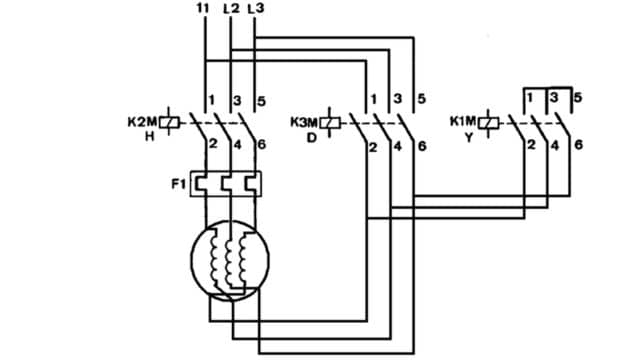
So, in simple terms, using a star-delta starter is like using a magic switch that gives the motor about 58% less voltage when it starts. This helps the motor begin gently, and then you switch it to normal mode for regular operation.
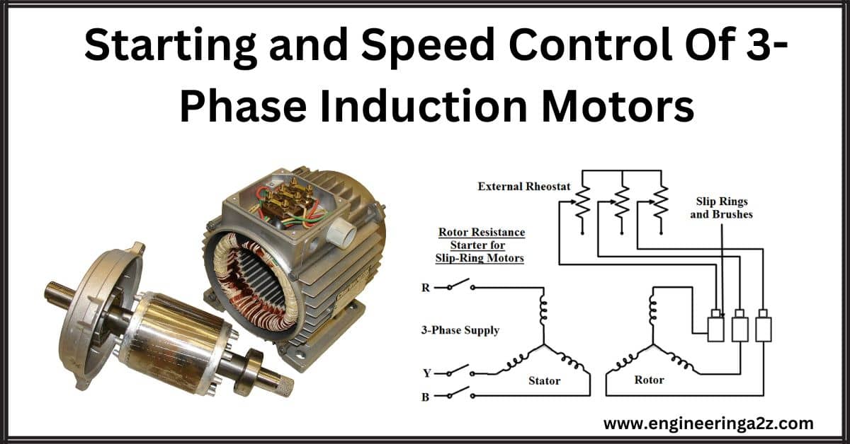
Starting Of Slip-Ring Motors
Slip-ring motors are a type of motor that can be started at full power right away. This is because they have a special feature called slip-rings, which allow us to easily add extra resistance to the rotor circuit.
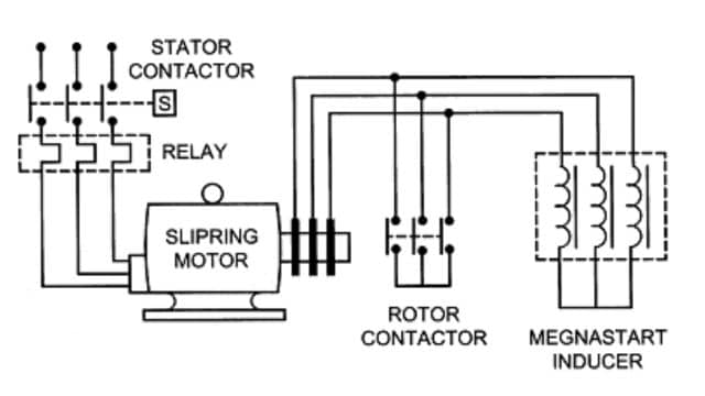
Now, adding this resistance to the rotor circuit has a few benefits. First, it reduces the amount of electrical current needed to start the motor, both in the rotor and the stator (the main part of the motor). Second, it makes the motor more efficient by improving something called the power factor. And third, it boosts the motor’s starting power, making it easier to get things moving.
You can control this resistance with a rheostat, which is like a dial that can be adjusted to change the amount of resistance. This dial can be turned by hand or adjusted automatically.
Because adding extra resistance in the rotor makes the motor start with more power, slip-ring motors can even be started when they already have a load to carry.
Speed Control Of Three-Phase Induction Motor
To control the speed of a three-phase motor, there are different methods we can use. These methods include things like changing the number of poles, adjusting the voltage that goes to the motor’s main part (stator), converting the frequency of the power supply, and using other devices like hydraulic couplers or electromagnetic slip clutches.
Now, here’s the simple part: The actual speed of a three-phase motor can be calculated using a formula. In this formula, the motor’s speed “n” depends on a few things. It depends on the motor’s basic speed “ns,” which is determined by its design. It also depends on the “slip” “s,” which is how much it’s slipping behind the basic speed. Lastly, it depends on the frequency of the power supply “f.”
So, in simple terms, you can change the speed of a three-phase motor by adjusting these things: the number of poles it has, how much it’s slipping (slipping), and the frequency of the power it’s getting.
n = Ns (1-s) = 120f/p(1-s)
n = actual speed of an induction speed
Ns = synchronous speed
f = frequency of the supply
P = number of stator poles
s = slip
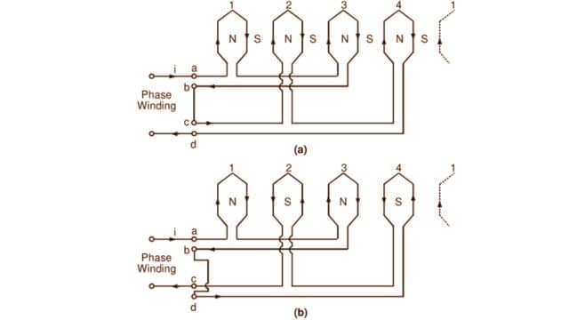
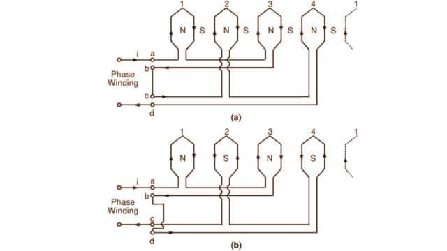
1. Pole-Changing Speed Control
You can adjust a motor’s speed by changing the number of poles in its stator winding. This method is commonly used with squirrel-cage induction motors.
Here’s what’s good about it:
- It provides strong and stable performance.
- It’s very efficient because there’s no energy wasted as heat.
- It’s easy to set up and control, and it’s cost-effective.
But there’s a catch – it doesn’t allow for super smooth speed changes because it adjusts in big steps. To make the speed changes smoother, you can combine it with other methods like changing the voltage or using an electromagnetic slip clutch. This way, you get both efficiency and smooth speed control.
This method is ideal for machines in manufacturing that don’t require very precise, stepless speed adjustments. Examples include metal cutting machines, elevators, cranes, fans, water pumps, and more.
2. Variable Slip Speed Control
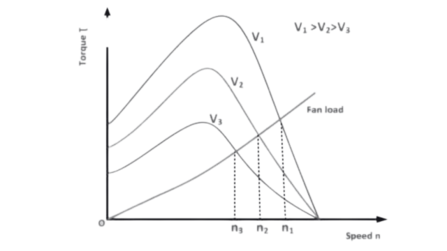
(i). Changing The Stator Voltage
In an induction motor, the twisting power it produces (called torque) is linked to the square of the voltage that goes to its main part (the stator). This means that if you change the stator voltage, you can also change how strong the motor is and how it behaves.
Now, here’s the catch: This method isn’t great for regular squirrel-cage motors because they have very low resistance in their rotor (the spinning part). When you lower the voltage to make the motor slower, the current going through it increases a lot, which can be a problem.
But, it can work for a different type of motor called a wound-type induction motor. You can add some extra resistance or special devices in the rotor circuit to control the heat generated by the motor. This way, you can adjust the voltage, change the motor’s behavior, and keep it from overheating.
(ii). Changing The Rotor Resistance
This way of controlling speed only works for a certain type of motor called a wound motor. Inside this motor, there’s a part called the rotor, and you can put some extra resistance in its circuit. When the load on the motor stays the same, if you increase the resistance, the motor goes slower. If you reduce the resistance, it goes faster.
This method is pretty straightforward to use, easy to control, and doesn’t cost a lot to set up initially. But there’s a downside – when you use more resistance, the energy that the motor loses and turns into heat. Also, the motor’s behavior when you do this is gentle, not abrupt.
So, in simple terms, this speed control method only suits a particular type of motor, and it’s like adjusting a knob to make it go slower or faster. It’s simple and doesn’t cost much, but it makes the motor lose energy as heat and has a gentle effect on how the motor behaves.
(iii). Cascade Speed Control
Cascade speed control, which uses a circuit with SCR (Silicon Controlled Rectifier) inverters, offers several benefits. It provides better control over the motor’s behavior, has low voltage loss during conversion, takes up little space, doesn’t have any moving parts, operates quietly, and is easy to maintain. This method is suitable for wound-type motors.
However, it has a drawback. To filter out unwanted effects, it includes a reactor in the rotor circuit, which lowers the power factor of the system. In simpler terms, it’s not as efficient in how it uses electrical power.
3. Variable Frequency Speed Control
To control the speed of an induction motor, you can change the frequency of the power it gets. This is a cost-effective way and is quite popular for controlling the speed of these motors.
Variable frequency speed control is a method where you adjust the power frequency going to the motor’s stator, which then changes how fast it runs. To do this, you use a device called a frequency converter or variable frequency drive (VFD). There are two types of VFDs: AC-DC-AC and AC-AC.
Modern VFDs use digital technology, are getting smaller, and are becoming more reliable and precise. When you use them, you can:
- Control the motor’s speed very precisely.
- Get complete protection for the motor and easily diagnose any issues for simple maintenance.
- Start the motor directly, which means it can start with strong twisting power and a low initial current. This is good for the power supply and equipment, and it can even save you from needing a separate soft start device.
- It has a high power factor, which is efficient and can save energy, so you don’t need extra equipment like capacitors.
In simple terms, variable frequency speed control is a great way to adjust a motor’s speed smoothly and efficiently, while also protecting it and being friendly to the power grid.
Frequently Asked Questions (FAQs)
-
What are the two applications of a shaded pole induction motor?
1. Refrigeration and Freezer Fans: Shaded pole induction motors are commonly used in the evaporator fans of refrigerators and freezers. These motors are responsible for circulating cool air inside the appliance to maintain a consistent and low temperature. Shaded pole motors are suitable for this application due to their simplicity, reliability, and cost-effectiveness.
2. Small Appliance Fans: Shaded pole motors are often found in various small appliances that require air circulation or cooling. This includes applications like desk fans, exhaust fans, and bathroom ventilation fans. These motors are well-suited for these applications because they are compact, easy to control, and can provide the necessary airflow for cooling or ventilation purposes in smaller devices. -
In which direction does a shaded pole motor run?
A shaded-pole motor typically runs in one direction, determined by its design. Reversing its direction is challenging due to its shading coil setup and stator pole arrangement.
-
What kind of motor is used in a mixie?
Mixies typically use universal motors, which are compact and versatile, capable of high-speed blending and grinding due to their ability to operate on both AC and DC power sources.
Read Also:
- Starting Methods of 3-Phase Induction Motor
- Three Phase Induction Motor | Construction & Working Principle
- No load or Blocked Rotor Test on Three Phase Induction Motor
- Single Phase Induction Motor | Double Revolving Field Theory
- Single Phase Induction Type Energy Meter


Leave a Reply