Table of Contents
Circuit Theorem
The circuit theorem is basically defined as the arrangement of voltage source (Vs), resistance and other circuits elements is called a network. A network as shown in figure is a simple one and can be solved for finding out voltage or current of any element by the application of simple law i.e., Ohm’s law. However network shown in figure is such that only Ohm’s law is sufficient to solve this network.
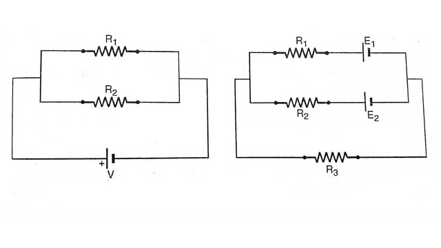
So other laws known as Kirchhoff’s laws are used for solving this type of network. In many circuits, application of these laws don’t give quick and easy solution, so to overcome this difficulty other network theorems and techniques have to used. These theorems are :
- Thevenin’s Theorem
- Norton’s Theorem
- Superposition Theorem
- Maximum Power Transfer Theorem
By the uses of the above theorem complicated network can be reduced to simple circuit and analysis of the circuit becomes easy and simple.
Thevenin’s Theorem
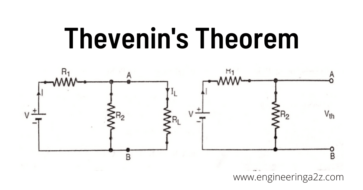
As per Thevenin’s theorem, any two terminal network containing a number of emf sources and resistance can be replaced by an equivalent simple series circuit of one voltage source and one resistance. The voltage and resistance are called Thevenin’s equivalent. These are denoted by VTh (Thevenin’s Voltage) and RTh (Thevenin’ resistance).
Procedure for finding Thevenin’s Equivalent
Consider a network as show in figure. It is used to find the current IL through load resistance RL connected across two terminals A & B.
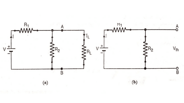
Step 1 : Finding open circuit voltage VTh
(1) Remove the load resistance RL connected between terminals AB of networks.
I = V/R1 + R2
VTh=Voltage between terminals A, B = IR2
or VTh = (V/R1 + R2) x R2
Step 2 : Finding Thevenin’s equivalent resistance
The Thevenin equivalent resistance is the between the terminals AB while looking into the circuit with the conditions
(a) Load RL is removed.
(b) Emf is reduced to zero and the circuit can be redrawn as shown in figure.
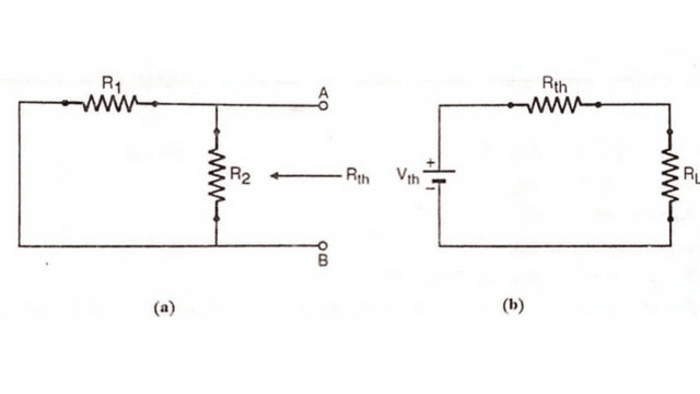
RTh = R1 x R2/R1 + R2
Thus the value of the RTh is determined. Once the value of VTh and RTh are known, then the current through load resistance RL is determined by connecting the load resistance. RL between terminal A and B as shown in figure.
IL = VTh/R1 + R2
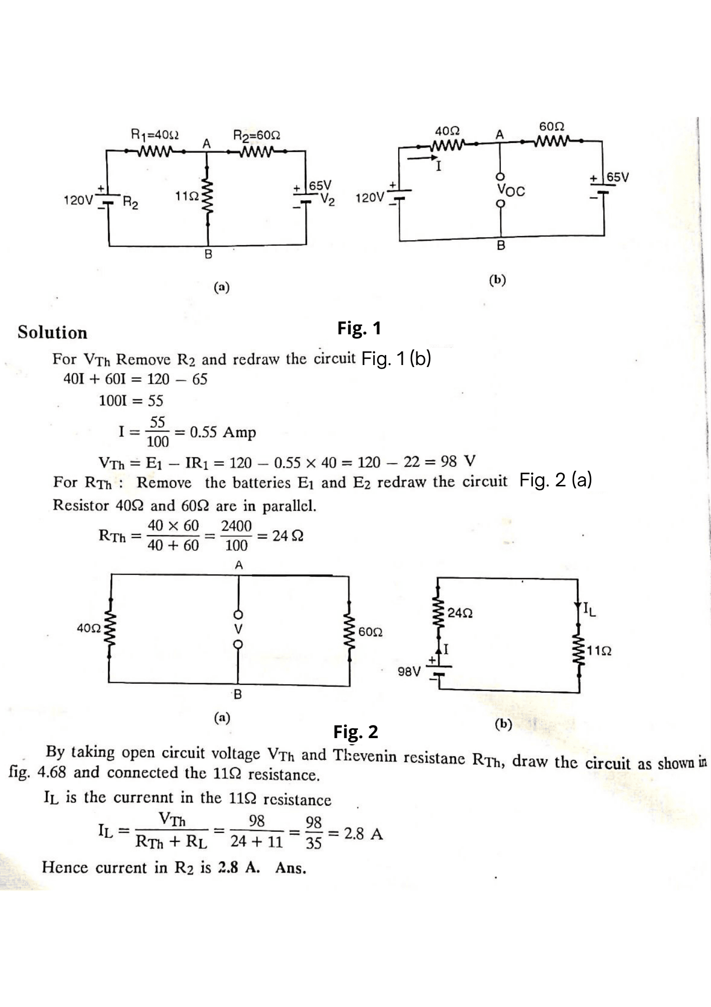
Example :- Find the current in R2 when R2 = 11 ohms. Using Thevenin’s theorem as shown in figure?


Leave a Reply