
Table of Contents
Megger
The most portable insulation tester is Megger. It is used to test extremely high resistance in the megaohm range. Megger is expert in ground earth testing. It gives high accuracy. This test is easy to use and having light weight. Megger is used to determine the leakage current and verifying the insulation level.
Construction of Megger
It is made up of two major components: a DC generator and an ohm-meter. The hand rotated generator rotates at roughly 140 to 160 rpm and generates voltages of 500 to 1000 V or 2000 V, as specified by the megger’s design. It’s also known as a dynamo generator or a magneto generator. Figure shows a megger’s circuit diagram
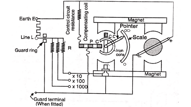
The magnetic field for both i.e., generator as well as meter is provided by the permanent magnets. The moving system of megger consists of three coils: current coil, pressure coil and compensating coil, which are mounted rigidly on a pivoted shaft which are free to rotate over a C-shaped iron core. The coils are connected to the circuit by means of flexible wires (ligaments), that exert no restoring torque on the moving system. Hence the moving system may take up any position over the scale when the generator handle is stationary.
Between the generator terminals and the test terminals marked L and E, the current coil is connected in series with the resistance R. A heavy current flows through the current coil when the terminals are short-circuited and the generator handle is moved. The instrument’s range is also controlled by resistance R. The P.C. is connected across the generator terminals in series with a compensating coil and a protection resistance R. To obtain better scale proportions, a compensating coil is included.
When current from the generator passes through P.C., the coil tends to align itself with the permanent magnet’s field. No current flows through the deflecting coil when the test terminals L and E are open, equating to infinite resistance. The torque created turns the megger’s moving system until the scale reaches infinity, indicating that the external circuit’s resistance is much too high for the instrument to measure.

The ohm-meter, which measures resistance in mega ohms, is another component of the instrument. It is made up of two moving coils that are positioned at an angle to each other. These coils rotate between two poles of a permanent magnet with the help of a spindle and jewels.
Both the current coil and the pressure coil are made of fine wire with a few turns and are linked to the circuit via series and parallel resistances R1 and R2 as shown in the diagram. The centre of both coils has a pointer that indicates the reading on the scale from infinity to zero. L and E are the two terminals on Megger.
Principle of Megger
The megger operates on the ratiometer/ohmmeter principle. Both the system voltage and current generate the required deflecting torque. The deflecting torque is produced by the interaction of the magnetic fields produced by the voltage and current. The required coils are arranged in such a way that the deflecting torque is proportional to V/I.
Between the test terminals L and E, the resistance under test is connected. The generator handle is then rotated at an uniform speed. The handle must be turned continuously until the pointer delivers a consistent reading. The resistance on the scale is measured in mega ohms.
Megger Testing Procedure
- The measuring resistance is connected across the test terminals, i.e., in series with the deflecting coil and across the generator. When current is given to the coils, then torques in opposite directions occur.
- No current will pass through the deflecting coil if the resistance to be measured is high. As a result, the controlling coil will position itself perpendicular to the magnetic axis, bringing the pointer to infinity.
- When the resistance to be measured is low, a large current flows through the deflecting coil, causing the torques to set the pointer to zero and infinity. When the testing terminals L and E are short-circuited with a low resistance, a large current flows through the deflection coil or current coil, producing sufficient torque to overcome P.C.’s anti-clockwise torque. The moving system is set to zero, indicating that the external resistance is too small to be measured by the instrument.
- The pointer is placed between zero and infinity for intermediate resistance values, depending on the torque produced. When a resistance under test is connected between terminals L and E, the opposing torques of the coils balance each other, causing the pointer to come to rest at some intermediate point on the scale, directly indicating the resistance under test’s value.
- The hand-operated generator is a permanent magnet generator with a voltage range of 500 to 2500 volts.
- The guard ring is used to shunt leakage current across the test terminals, i.e. within the tester and the generator’s negative terminal, rather than going through the current coil, so reducing the error caused by it. This guard ring can be connected to a guard wire on the insulation under test through a ground termination, which is usually provided.
Frequently Asked Question (FAQs)
-
What is a megger?
Megger is an instrument which is used for measurement of very very high resistance i.e. , mega ohms. It essentially consists of a hand driven DC generator and truely a direct reading ohm meter.
-
What is an earth tester?
An Earth Tester is a special type of megger which sends AC through earth and DC through the measuring instrument. It has four P1, C1, P2 and C2 terminals outside the instruments. The two terminal P1 and C1 are short circuited to form a common point which is connected to the earth electrode during test. The other two terminals P2 and C2 are connected to the other two auxiliary electrodes .
-
How many types of megger?
There are two types of megger:-
1.Manual type (Hand Operated)
2.Electronic Type (Battery operated)
Related Posts
- BTech ECE Previous Year Question Papers PDF – Semester Wise Download

- Digital Electronics Notes PDF (Handwritten) | Engineeringa2z

- Pulse Code Modulation (PCM) | Block Diagram, Advantages and Applications

- What is HDI PCB? And its Characteristics, Microvias and Advantages

- Top 5 Benefits of Using Turnkey PCB Assembly

- How to Reduce PCB Assembly Costs Without Compromising Quality


Leave a Reply