Table of Contents
Introduction of Magnetic Field
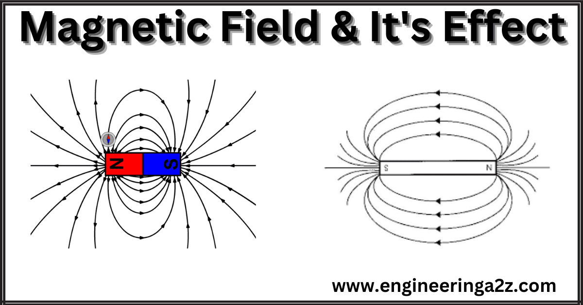
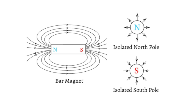
The area around a magnetic pole or a magnet within which ,its influence is feel or can be seen , is called its magnetic field. A small compass needle can be used to map a magnetic field. Iron filings may also be used to demonstrate the shape and distribution of the magnetic field in any horizontal plane. These filings set themselves in the form of curved chains between the poles as shown in figure. Such continuous curves in a magnetic field are normally termed as magnetic lines of force. These lines of force travel from the north to the south pole as shown in below. Thus each line of force forms a closed path.
Magnetic Effect of Electric Current
When an electric current flows through a conductor, magnetic field is set up all along the length of the conductor. Figure shows the magnetic field produced by the current flowing in a straight conductor. The magnetic lines of force are in the form of concentric circles around the conductor.
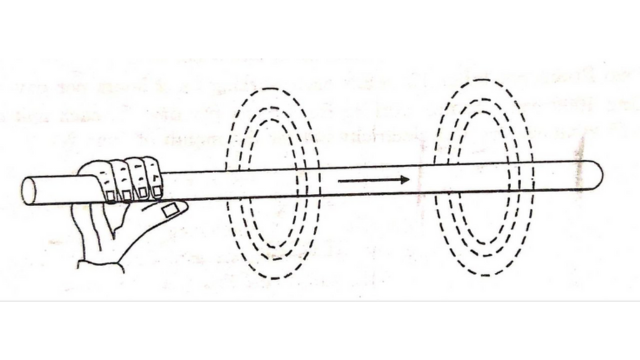
The direction of lines of force depends upon the direction of current and may be determined by right-hand rule. Hold the conductor in the right hand with the thumb pointing in the direction of current as shown in above figure. Then the fingers will point in the direction of magnetic field around the conductor. Applying this rule to above figure, it is clear that when viewed from left hand side, the direction of magnetic lines of force will be clockwise.
The following points may be noted about the magnetic effect of electric current :
- Higher the current flowing through the conductor, stronger is the magnetic field and vice-versa.
- The magnetic field near the conductor is stronger and becomes weaker as we move away from the conductor.
- The magnetic lines of force around the conductor will be either clockwise or anticlockwise, depending upon the direction of current. One may use right-hand rule to determine the direction of magnetic field around the conductor.
Magnetic field due to Solenoid
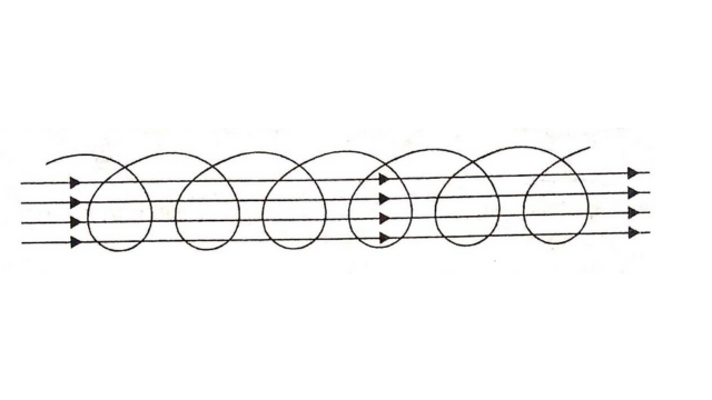
A solenoid is a long straight core having a coil wound on it. A magnetic field is produced in a solenoid when current is passed through the wire .The below figure shows a solenoid, the magnetic field produced due to flow of current.
Assuming a uniform flux density over the entire cross section area A of solenoid, Flux through the solenoid = Φ = B.A = μ0 μr NIA/length Weber
If the solenoid is an air solenoid, then μr = 1
∴ Φ = μ0NIA/length Weber
A solenoid behaves like a bar magnet when current is flowing through it. Looking from one end, if current flowing through turns of coils is clockwise, there is South pole at the near end while the farther end is a North pole. If current flowing through the coil is anticlockwise, the near end is a North pole, while the farther end is a South pole.
The direction of magnetic lines of force can also be found by using Right hand Thumb rule ie. Hold the coil so that fingers of right hand point in the direction of flow of current through turns of the coil, then thumb will point in the direction of magnetic field in the Centre of coil.
Magnetic Field Around a Straight Conductor
If a current I flows through an infinitely long straight conductor, there will be magnetic lines of force around it. These will be in the form of circles around the conductor as shown in the figure. Their plane is perpendicular to the conductor and their centres will be at the centre of the straight conductor.
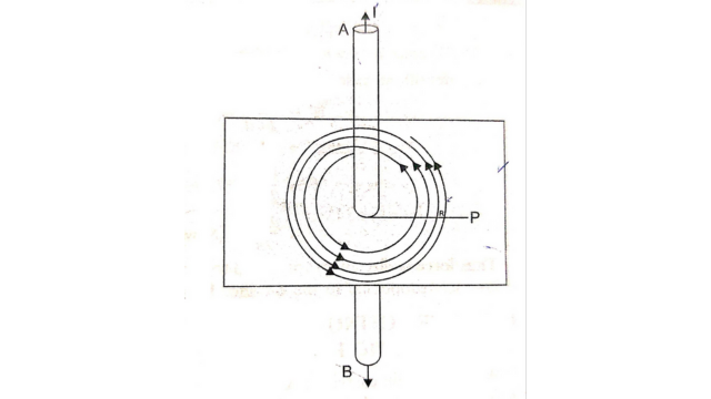
At a point P. baving a distance from the centre of conductor, field strength H can be found by placing a unit north pole at this point. If the unit north pole is moved once around the conductor against this force, the work done will be
m.m.f = force x distance =1
∴ I = H x 2πr joules
H = I/2πr A/m If there are N conductors as such
than H = NI/2πr A/m
B = μ0NI/2πr Wb/m2
Force Between Two Parallel Current Carrying Conductors
Let A and B be two conductors, placed parallel to each other. Both the conductors will produce a magnetic field around itself when a current is passed through them. If current through them flows in the same direction, field strength in the space between them will decrease because of the opposite direction of magnetic flux produced by them in this space. Thus there will be a force of attraction between them as per the position shown in figure.
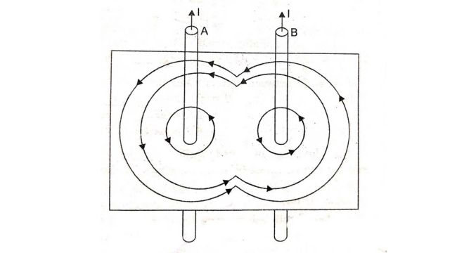
If current flowing through the conductors flows in the opposite directions. The direction of magnetic flux produced by one of these will be reversed. Thus there will be an increase in the magnetic flux in the space between the two conductors. It will result in production of a force of repulsion between the two conductors.
Hence two parallel current carrying conductors will
- Have force of attraction between them if current flowing through them is in the same direction.
- Have force of repulsion between them if current flowing through them is in opposite direction.
The magnitude of this force of attraction/repulsion depends upon :
- Magnitude of current flowing.
- Length of conductors.
- Distance between conductors.
Flux density at a point on conductor B due to A is
B = μ0I1 / 2πd Wb/m2
Force acting = BI2L Newtons where Lis the length of conductor .
F = μ0I1I2 L / 2πd Newtons
Thus force is directly proportional to product of currents flowing and length of conductor and while it is inversely proportional to the distance between them.
Force Acting On a Current Carrying Conductor Placed In A Magnetic Field
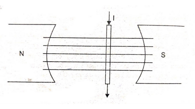
When a current carrying conductor is placed in a magnetic field, a force acts on it. The direction of force is perpendicular to the direction of current and field. As shown in figure a conductor AB is placed in the magnetic field at right angle to it. Flux density of field is B Wb/m² and a current 1 flows through it.
Let L be the length of conductor in m.
=> Force acting on it F = BIL = μ0 μr HIL newtons
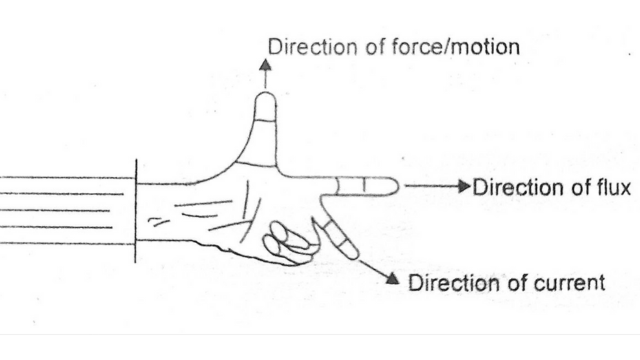
The direction of force acting on the conductor can be found by using Fleming’s left hand rule. It states that:
Hold the left hand such that the thumb, central finger and fore finger are at right angle to each other. If fore finger points in the direction of flux, central finger points in the direction of current, then thumb will point in the direction of force.
The direction of motion of conductor (if free to move) will be in the direction of force acting If the conductor lies in a direction, parallel to the lines of flux, no force acts on it. In general, on it. if conductor lies at an angle & with the direction of magnetic lines of flux, the force
==> F = BILsinθ newtons
Frequently Asked Questions (FAQs):-
-
What is a magnetic circuit?
A magnetic circuit is a closed path or loop through which magnetic flux flows. It consists of magnetic materials, such as iron or steel, and may include other components like coils, cores, and permanent magnets. Similar to an electric circuit, a magnetic circuit allows the control and manipulation of magnetic fields
-
What is magnetic flux?
Magnetic flux refers to the quantity or strength of magnetic field lines passing through a given area. It is represented by the symbol Φ and is measured in units called Weber (Wb). Magnetic flux is directly proportional to the magnetic field strength and the area perpendicular to the magnetic field.
-
What is magnetic field?
The area around a magnetic pole or a magnet within which ,its influence is feel or can be seen , is called its magnetic field.
-
What is magnetic flux density?
Magnetic flux density, represented by B, indicates the concentration or density of magnetic field lines in a given area. It is measured in units of tesla (T) or gauss (G). Magnetic flux density is directly related to the magnetic field strength and the permeability of the material.
-
What is reluctance in a magnetic circuit?
Reluctance is the measure of opposition encountered by a magnetic circuit to the flow of magnetic flux. It is analogous to electrical resistance in an electric circuit. Reluctance is influenced by the dimensions, material properties, and geometric arrangement of the magnetic circuit components. It is denoted by the symbol R and is measured in units of ampere-turns per weber (A/Wb) or oersteds per gauss (Oe/G).
-
What is unit of magnetic field?
The unit of magnetic field is the tesla(T). One tesla is equal to one weber per square meter (1T = 1Wb/m2)
Read Also:
- Single Phase Induction Motor | Double Revolving Field Theory
- MHD | Magneto Hydro Dynamic Generation
- Relay | Construction and Working
- Induction Heating and its Types
- Basic Electrical Engineering | Engineeringa2z
- Starting Methods of 3-Phase Induction Motor


Leave a Reply