Table of Contents
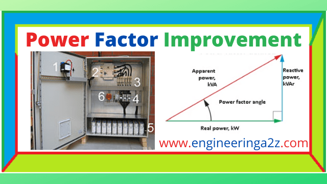
Power Factor Improvement
As we know that low power factor is almost due to the inductive load. The value of this power factor lies between 0.8 to 0.9 lagging. Sometimes when there is heavy inductive load, the value of power factor falls below 0.8. To improve such cases we should use load that is to connected to device which take the leading reactive power. This can be achieved by employing the following equipment.
- Static capacitor
- Synchronous Condensers
- Phase advancers
Power Factor Improvement By Using Static Capacitors
Power Factor Improvement
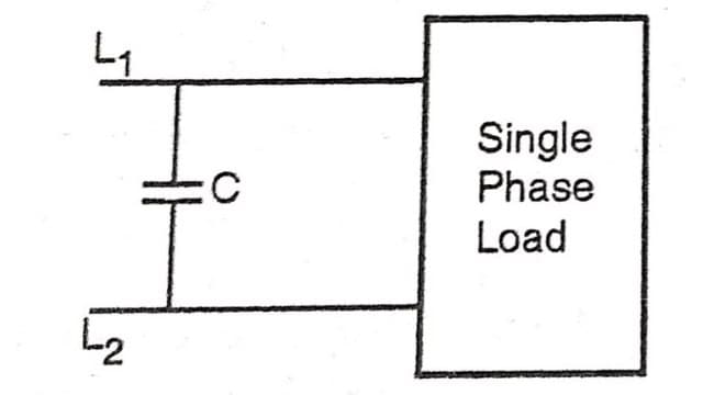
The low power factor is generally due to inductive load in nature and also take the current at lagging power factor. In order to improve (raise) the power factor. a static capacitor is connected in parallel with the load. This static capacitor draws the current which leads the voltage and neutralizes the lagging wattless component partly or completely .
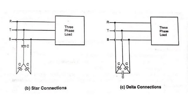
For three phase loads or 3 phase induction motors, the capacitors can be connected in star or delta as shown in figure.
Generally, in practice the capacitors are connected in delta because in delta connections, the size of the capacitor will be one third of the size in star connections. There is not much power lost in the capacitor and also they need not much maintenance and are also available in small size.
Consider an inductive load as shown above in the circuit diagram. The load current I lags by angle Φ₁ .
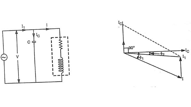
The parallel connected capacitor C with load current Ic leads the voltage by 90°. The resultant current I1 is the vector sum of the two currents I and Ic and its angle of lag is now Φ₂ , which is less than Φ₁ . The value of cos Φ₂ is more than cos Φ₁ . Hence the power factor of load is improved from cos Φ₁ and cos Φ₂.
Advantage Of Improved Power Factor By using Static Capacitors
- Small conductor size.
- Small copper loss and better efficiency.
- Less voltage drop, better regulation.
- For the same kW output, smaller is the kVA rating of the equipment.
Disadvantage Of Improved Power Factor By using Static Capacitors
- They have short service life from 8 to 10 years.
- They are damaged quickly when the voltage exceed the rated voltage.
- The damaged capacitor can not be repaired.
Power Factor Improvement By Using Synchronous Condenser
The synchronous motor, when over excited takes a leading current and therefore it behaves like a capacitor. An over-excited synchronous motor working at no load is called Synchronous condenser.
When synchronous motor is used for improving the power factor, it is connected in parallel with the supply. It takes a leading current which partly neutralises the lagging reactive component of the load. Thus the power factor is improved.
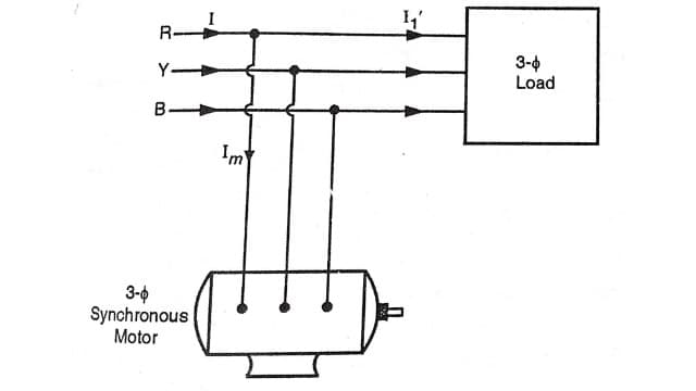
Above fig. shows the circuit diagram for power factor improvement by synchronous condenser method. The 3-phase inductive load takes a current of I1‘ at low lagging power factor cos Φ₁’. The synchronous condenser draws a current of Im which leads the voltage by an angle Φm. The resultant current I is the vector sum of I₁’ and Im and resultant current I lags the voltage by an angle Φ₂ .
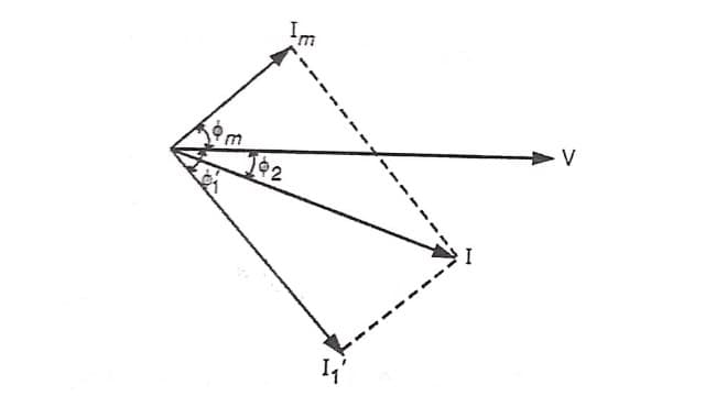
It is very much clear from the phasor diagram that angle Φ₂ is less than the angle Φ₁’. So that cos Φ₂ is greater than cos Φ₁’. Thus the power factor is improved from cos Φ₁ to cos Φ₂. Synchronous condensers are used to improve the power factor of the load above 500 kVA. These are generally used at major bulk supply substations for power factor improvement.
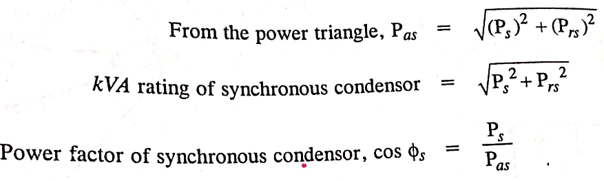
Calculations for finding the rating of synchronous condenser
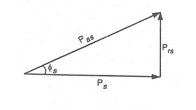
Let “P” be the active power of the load and cos Φ₁ is the power factor. If the power factor is to be improved to cos Φ₂ , when the synchronous condenser is drawing active power Ps from the supply, then the rating of the synchronous condenser and the power factor at which synchronous condenser is operating can be determined as follows. The power triangle of the load is shown in Figure
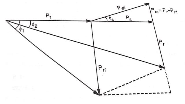
Reactive power of the load Pr₁ = P₁ tan Φ₁
When synchronous condenser is connected in the circuit
Then, total load (Active power), P = P₁ + Ps
Total reactive power, Pr = P tan Φ₂
Reactive power supplied by the synchronous condensor Prs = Pr – Pr₁
Advantage of improved power factor using synchronous condenser
- By varying the field excitation of the synchronous motor, the power factor of the motor varies, thus the magnitude of current drawn can be changed. By improving the power factor, current drawn by the motor decreases, provided supply voltage and power input remain constant.
- Due to less current, small conductor size is required.
- Less voltage drop and better regulation is achieved.
- For same kW output power, smaller kVA rating of various equipment of the power system helps in the cost reduction.
Power Factor Improvement By Using Phase Advancers
These are used to improve the power factor of induction motors. The power factor of an induction motor is low because the exciting current lags behind the voltage by almost 90°. This power factor can be improved by fitting a set of A.C. exciter or phase advancer, which supplies the exciting current to the rotor at slip frequency. Such an exciter can be mounted on the same shaft as that of the motor or it can be suitably driven from it. By providing more ampere turns than required, the induction motor can be made to operate on leading power factor like an over-excited synchronous motor. Use of phase advancers is generally not economical for a motor size below 200 H.P.
Location of Power Factor Improvement Equipments
The most appropriate location for the installation of power factor improvement equipment is the place where the apparatus responsible for low power factor is installed.
In case of transmission lines, if the power factor is to be improved by installing synchronous condensers, the correct location for installing the power factor improvement equipment is the receiving end of transmission lines i,e, receiving sub station, so that it is not only the generators and transformers which carry the reduced current as a result of improved power factor, but the transmission line is also relieved of carrying excessive current.
In case, the synchronous condensers are installed near the generators, then only the generators will carry the reduced current but the transmission line may have to still carry the excessive current due to its own low power factor.
Read Also :
- Power Factor Meter | Dynamometer Type
- Power Factor | Concept | Importance and Reason of Low Power Factor
- Basic Electrical Engineering | Engineeringa2z


Leave a Reply