Table of Contents
Inverter
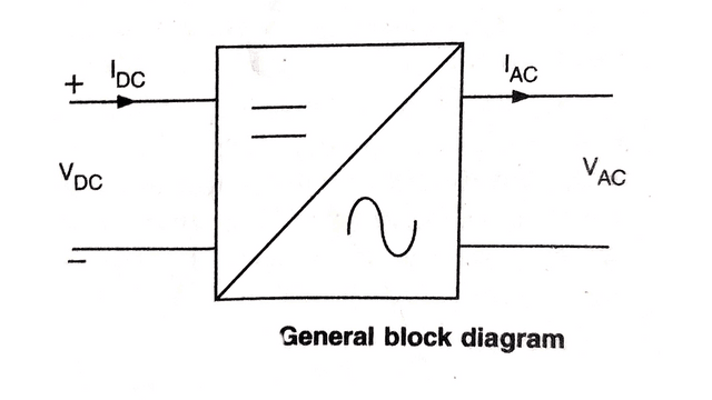
Inverter is a static electrical device which is used to convert DC power into AC power by switching the Dc input voltage in a predetermined sequence so as to generate AC voltage output. Now in simple inverter circuit, DC power is connected to a transformer through the centre -tap of the primary winding. A switch is rapidly switched back and to allow current to flow back to the DC source following two alternate paths through one end of the primary winding and then the other. The alternation of the direction of current in the primary winding of the transformer produces alternating current (AC) in the secondary circuit.
Working of Inverter
It consists of a transformer whose primary winding is centre tapped connected with a switch and a battery. Voltage applied to primary is DC in nature. When the switch is connected to above shown position; the direction of current flow in primary winding is from top to bottom. Whereas when switch is connected down at position 2, the current flows from bottom to top. This change in the direction of current flow in the primary winding gives rise to an alternating voltage in it. The frequency of this alternating voltage will depend on how rapidly the switch positions are inter-changed. Alternating voltage at primary induce an alternating emf in the secondary winding which act as the AC output.
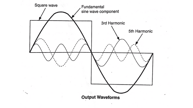
The switch in the simple inverter described above produces a square voltage waveform as opposed to the sinusoidal waveform that is the usual waveform of an AC power supply. Using Fourier analysis, periodic waveforms are represented as the sum of an infinite series of sine waves. The sine wave that has the same frequency as the original waveform is called the fundamental component. The other sine waves, called harmonics that are included in the series have frequencies that are integral multiples of the fundamental frequency.
You may also like


Types of Inverter
- Series Inverter
- Parallel Inverter
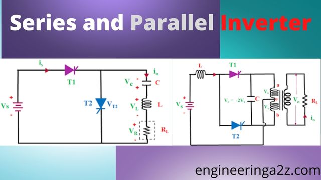
Series Inverter
In series inverter the thyristor are connected in series. It uses class A commutation method. In series inverter the commutating elements L, C and R are connected in series. It forms a RLC resonant circuit.
Principle of Series Inverter
The heart of the inverter circuit is the resonant circuit. It is formed by suitable combination of inductor/capacitor with resistor of required value. In order to produce a sinusoidal output, this type of inverter is frequently designed considerably under-damped, and is driven with a very small conduction gap (assumed negligible) between the extinction of one SCR and the firing of the other one. Series inverters are characterised by the load impedance capacitive at low frequency and inductive at high frequency. The transition frequency between being capacitive and inductive is the resonant frequency, a. at which frequency the L-C-R load circuit appears purely resistive and maximum power is transferred to the load, R.
The basic oscillation producing damped oscillation by the tank circuit is by R² < (4L/C)
Working of Series Invertor
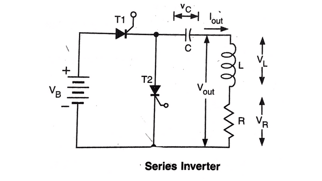
The commutating components L & C are selected such that they together with the load form an under-damped circuit. Both the SCRs T1 & T2 are turned ON alternatively at some interval. It is to be noted that under no circumstances; both the SCRS should be turned ON simultaneously. Otherwise it will cause the short circuit.
The capacitor in series with the load causes natural commutation to occur, and also forces the average (not the effective or RMS) load current to be zero. So this is the self commutating circuit. Capacitor will help to turn OFF the SCRs. The capacitor has an external path through which to release its stored energy. The parallel resonant circuit can release its stored inductive energy within its parallel circuit, without an external circuit.
The stored energy can internally resonate, transferring energy back and forth between the L and C. gradually dissipating in the circuit R, as heat. Because of this fact, the load current lout and voltage Vout are independent of the location of the return lead from the load. It can be returned to either end of the DC source. In this circuit; L is large enough that the circuit is under-damped oscillatory (ie., L> R2*C/4R)
- Let the initial voltage across capacitor (i.e., Vc) is negative. The output voltage (across L and R) now goes negative before the current decreases to the holding current and turn-off occurs.
- DC voltage is applied to the circuit with polarity shown in figure.
- SCR T₁ comes in conduction mode after giving the external gate pulse to its gate at t=0. At the same time SCR T₂ is OFF.
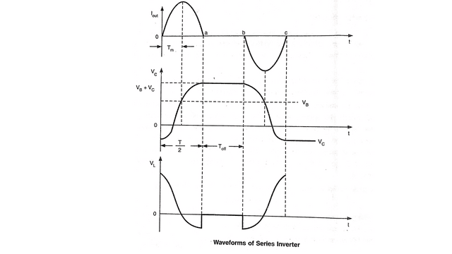
- Resonating current I(out) starts to flow through the circuit via SCR T₁, C, L & R and capacitor starts charging. Consequently, the capacitor is charged to a voltage in excess of VB. The phase of current flowing through the load is same as the voltage across it.
- The resonating current Iout flows for a half cycle up to point ‘a’. At this point: T₁, will be turned OFF because the current flowing through it becomes zero. C will be charged to VB + VC at this point.
- A little time gap shown in waveform (ab) is due to time gap to turn OFF the T₁, and Turn ON the T₂. This time gap is called “Dead time”. During this period because both SCRS T₁, & T₂ are OFF, voltage across capacitor does not find any path to discharge so remains same. Also Voltage across load and inductor are zero.
- At point ‘b’ (in waveform) SCR T₂, is fired and capacitance C will discharge through L, R & T. Current will be in opposite direction and again becomes zero at point c (in waveform), SCR T₂ will be turn OFF.
Parallel inverter
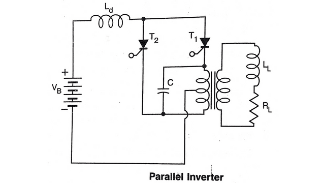
In parallel inverters the thyristors are connected in parallel. In parallel inverter the capacitor is connected in parallel with the load. Parallel inverts are used for low frequency applications. The voltage source Vb is connected in between the common cathode point and the centre tap. The inductor Ld in the DC circuit is required to prevent excessive spikes of current from being drawn by C when switching occurs.
The commutating capacitor effectively resonates with the load, thereby absorbing the energy stored by L1 each half cycle. Current does not automatically decrease below the holding current to achieve turn-off. However, when the next load-carrying SCR is fired, the commutation capacitor is connected so that its voltage reverse biases the SCR which had been conducting, causing it to turn-off.
Complementary commutation permits the parallel inverter to be operated with variable pulse widths and at somewhat higher frequencies than the corresponding series inverter. However, the circuit is not self-starting. Special arrangements must be made to establish an appropriate initial charge on C so that the first SCR can be turned off after the first half cycle. The circuit also cannot be turned off by simply removing the firing pulses.
Working of Parallel Inverter
- Initially SCR T₁, is triggered on and the voltage across it will falls to almost zero. A current accompanied by an appropriate magnetic flux will rise in the top half of the transformer primary winding. This flux is common to both halves of the transformer winding.
- The source voltage V, would be induced in the lower half and the commutating capacitor would have a voltage of 2V across it.
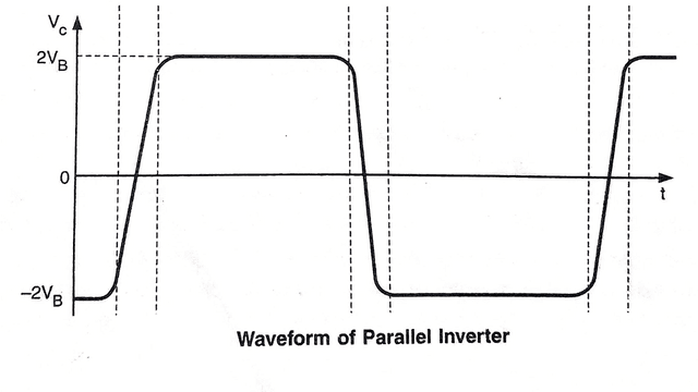
- Subsequently, when the SCR T₂, is triggered ON; the commutating capacitor C applies a voltage of approximately 2 V to appear across T₁, for a sufficient length of time. Soon the SCR T₁, will be turned OFF.
- SCR T₂, will now be conducting and a voltage of 2V will appear across the transformer primary and the commutating capacitor, but with a reverse polarity.
- At the next trigger pulse T₁, will be again turned ON and T₂ OFF.
Thus, if trigger pulses are periodically applied to the alternate SCRs, an approximately rectangular voltage wave will be obtained at the transformer output terminals.
Frequently Asked Questions (FAQs)
-
What are the application of Inverters?
Inverter are used in UPS(Uninterrupted power supply), Induction motor drives, Traction and HVDC etc..
-
What are the drawbacks of series Invertor?
The main drawbacks of series inverter are :-
1.Discontinuous current.
2.High distortion.
3.Poor output regulation.
4.Limited output Frequency.
Related Posts
- Amplifier | Classification of Amplifier
- Amplitude Shift Keying (ASK) | Its Types and Advantages
- B.Tech – Electrical Engineering Previous Year Question Papers Download

- Bipolar Junction Transistor (BJT): Types, Working, Construction, Advantages

- BTech ECE Previous Year Question Papers PDF – Semester Wise Download

- Cathode Ray Oscilloscope (CRO) Construction and Working Principle


Leave a Reply